
an aerodynamic device

An aerodynamic, wing shaft technology, used in transportation and packaging, aircraft parts, propellers, etc., can solve problems such as unsuitable vertical lift, complex structure, and inability to generate thrust

Active Publication Date: 2017-11-17
苏州市相城区黄桥工业园经济发展有限公司
View PDF6 Cites 0 Cited by
  • Summary
  • Abstract
  • Description
  • Claims
  • Application Information

AI Technical Summary

Problems solved by technology

[0002] The traditional wing used for aircraft is an integral structure, which can only produce lift but not thrust under the action of pulling force or thrust produced by the engine, and the large lift of the wing with a small area can only be realized by increasing the speed; the traditional helicopter The main rotor depends on the rotor head to adjust the angle of attack and waving state of the blades to adjust the direction of lift. The structure is complex and the efficiency of generating lift is low.
Traditional wings are not suitable for heavy-load low-speed flight, let alone vertical lift

Method used


Image

  • an aerodynamic device
  • an aerodynamic device
  • an aerodynamic device

Examples


Embodiment Construction

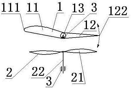
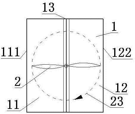
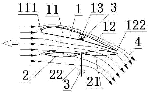
[0008] The present invention is now specifically described in conjunction with the accompanying drawings: an aerodynamic device, comprising a vane 1 , a propeller 2 and a bracket 3 . The vane 1 is located above the propeller 2 , and the vane 1 includes a front vane 11 , a rear vane 12 and a wing shaft 13 . The wing shaft 13 is parallel to the plane of rotation of the propeller 2 . The front wing 11 and the rear wing 12 are placed on the front and rear sides of the wing shaft 13 respectively, and the rear wing 12 can flexibly swing around the wing shaft 13 under the action of external force. Taking the horizontal plane as a benchmark, the front wing 11 is tilted at an angle of 10° in the front direction of the wing shaft 13; the rear wing 12 is at the rear of the wing shaft 13 and the maximum angle at which the wing shaft 13 turns upwards is 12°; the rear wing 12 The maximum angle that swings downward around the wing shaft 13 at the rear of the wing shaft 13 is 11°. The prope...


PUM


Abstract

An aerodynamic device belongs to the technical field of aircraft, and includes wings, a propeller and a bracket. The wings are located above the propeller, and include a front wing, a rear wing and a wing shaft; The wing shaft and the propeller rotation plane are parallel; the front wing and the rear wing are respectively arranged on the front and rear sides of the wing shaft; the rear wing under the action of external force can swing around the wing shaft flexibly; and with the horizontal plane as the base, the front wing tilts upwards in front of the wing shaft. The propeller comprises a propeller body and a propeller shaft; the propeller shaft is arranged on the bracket fixed on the wing shaft through a bearing; power drives the propeller to rotate; under the interaction of the propeller and wings, the device produces great thrust convenient to adjust the direction and level; and the level and direction of the thrust can be adjusted by adjusting the rotation speed of the propeller and the included angle of the rear wing and the horizontal plane. The device has the advantages of small resistance, high efficiency, high lift-drag ratio and strong mobility, and is applicable to vertical lifting heavy load low-speed aircraft.

Description

technical field [0001] An aerodynamic device belongs to the technical field of aircraft, and in particular relates to an aerodynamic device. Background technique [0002] The traditional wing used for aircraft is an integral structure, which can only produce lift but not thrust under the action of pulling force or thrust produced by the engine, and the large lift of the wing with a small area can only be realized by increasing the speed; the traditional helicopter The main rotor depends on the rotor head to adjust the angle of attack of the blades and the waving state to adjust the direction of the lift. The structure is complex and the efficiency of generating lift is low. Traditional wings are not suitable for heavy-load low-speed flight, let alone vertical lift. Contents of the invention [0003] The purpose of the present invention is to overcome the above-mentioned deficiency of traditional wing, invents a kind of aerodynamic device. [0004] An aerodynamic device c...

Claims


Application Information

Patent Timeline
Patent Type & Authority Patents(China)
IPC IPC(8): B64C11/00
Inventor 王志成
Owner 苏州市相城区黄桥工业园经济发展有限公司
Learn More