
A high-vacuum shut-off fan

A technology of closing the fan and high vacuum, applied in the direction of conveyor, conveying bulk materials, transportation and packaging, etc., can solve the problems of weakened sealing ability, failure to achieve sealing effect, stuck high-vacuum fan, etc., to prevent adhesion , Improve surface finish, good machining performance

Active Publication Date: 2019-07-23
CHANGZHOU YUTONG DRYING EQUIP
View PDF2 Cites 0 Cited by
  • Summary
  • Abstract
  • Description
  • Claims
  • Application Information

AI Technical Summary

Problems solved by technology

[0003] The current shut-off fan is composed of two parts, the casing and the impeller. The impeller and the casing maintain a small gap. However, with the increase of the use time, the wear of the impeller increases, and the sealing ability gradually weakens. When the wear reaches a certain amount, the sealing cannot be achieved. As a result, the entire high-vacuum shut-off fan needs to be replaced, and during normal use, if foreign matter enters, the high-vacuum shut-off fan is prone to jamming

Method used


Image

  • A high-vacuum shut-off fan
  • A high-vacuum shut-off fan
  • A high-vacuum shut-off fan

Examples


Embodiment 1

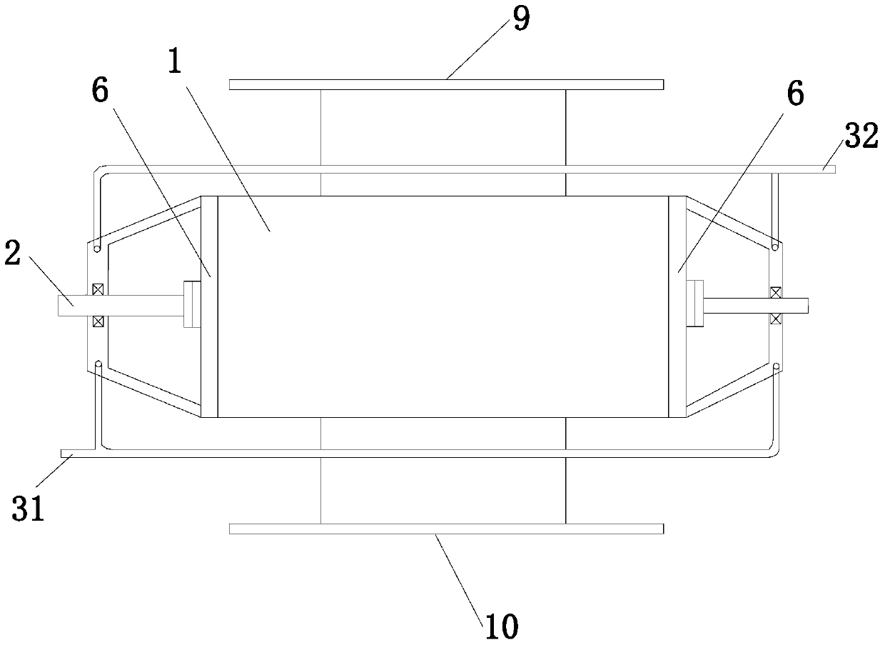
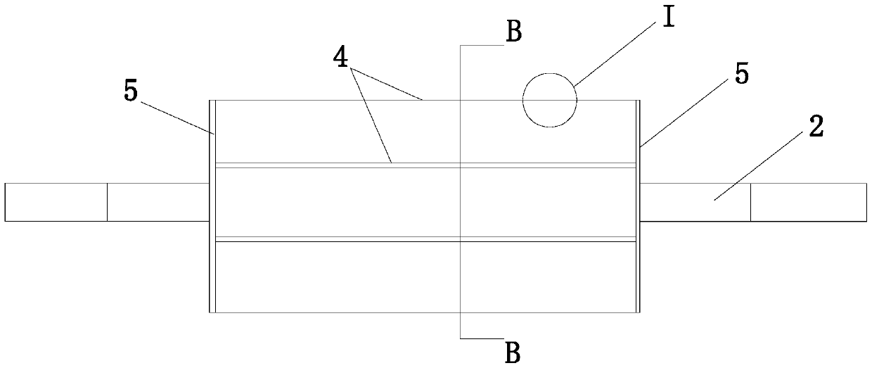
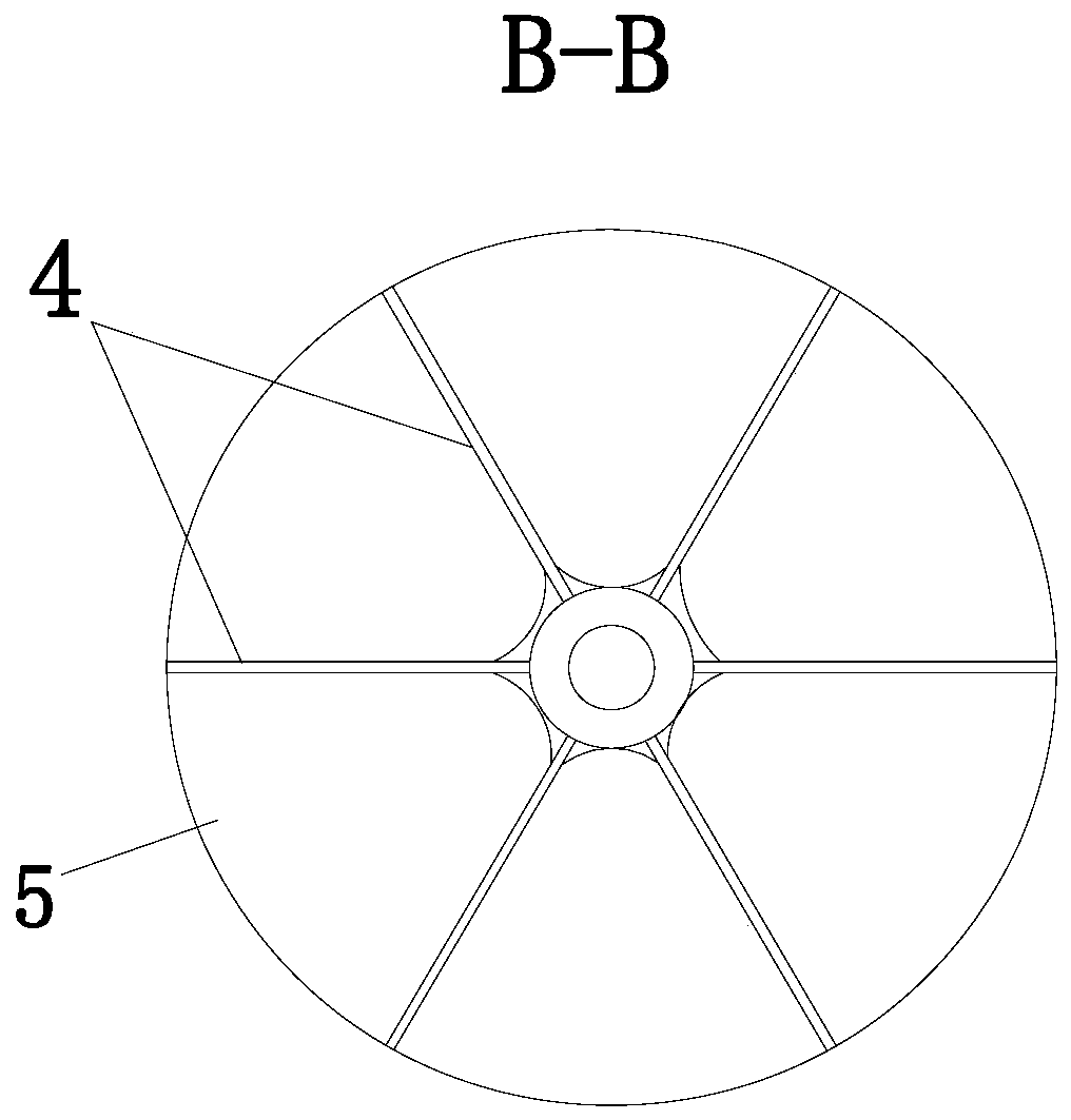
[0023] The air-to-high vacuum type shut-off fan of this embodiment includes: a cylindrical hollow housing 1 with an inner wall layer, the rotating shaft 2 runs through the housing 1 and the bearings are fitted on the end covers 6 on the left and right sides of the housing 1, the housing 1, and radially distributed on the rotating shaft 2, there are a plurality of wind-shielding plates 4, and the left and right ends of each wind-shielding plate 4 are respectively connected on a disc-shaped end plate 5, and the surroundings of the end plate 5, the The outer edge of the wind plate 4 is provided with a sealing strip that is sealingly matched with the inner wall of the housing 1 . The sealing strip includes: graphite: 20wt%; carbon fiber: 10wt%; PTFE: balance. Or, the sealing strip includes: 3-10wt% graphene, PTFE melts and wraps graphene under normal pressure and 330-340°C (the preferred solution is: graphene has multiple layers, and the phases are arranged in parallel and covered...


PUM


Abstract

The invention relates to a high vacuum type air lock. The high vacuum type air lock comprises a hollow shell with a cylindrical inner wall layer. A rotary shaft penetrates the shell and is matched with end caps on the left and right sides of the shell through bearings. A plurality of air partition plates are distributed in the shell and on the rotary shaft in the radial direction. The left and right ends of each air partition plate are connected to disc-shaped end plates respectively. Sealing strips in seal fit with the inner walls of the shell are arranged on the peripheries of the end plates and the outer edges of the air partition plates. Each sealing strip comprises 18-22 wt% of graphite, 8-12 wt% of carbon fibers and the balance PTFE. The sealing strips have a better machining property by being added with the carbon fibers, and the abrasion resistance of the sealing strips is improved; and meanwhile, as the graphite has the self-lubrication function, by means of combination of the graphite and the PTFE, the vacuum degree and the service life can be further ensured.

Description

technical field [0001] The invention relates to the field of material transportation, in particular to an auxiliary mechanical device for gas-solid two-phase separation. Background technique [0002] The shut-off fan is a mechanical device that hinders the passage of gas through small particles, powdery, and flake materials. It is often installed at the discharge port of the unloader working under negative pressure, and the upper part receives the material discharged from the unloader. , relying on the rotating impeller to transport the material, and also responsible for the sealing function to prevent the air from being sucked in from the discharge port during the pneumatic conveying process, so as to ensure the normal discharge of the unloader. [0003] The current shut-off fan is composed of two parts, the casing and the impeller. The impeller and the casing maintain a small gap state. However, with the increase of the use time, the wear of the impeller increases, and the...

Claims


Application Information

Patent Timeline
Patent Type & Authority Patents(China)
IPC IPC(8): B65G53/46
Inventor 张二年张玉陆文光臧德耿
Owner CHANGZHOU YUTONG DRYING EQUIP
Learn More