Leak detection method of underground diaphragm wall

A technology of underground continuous wall and detection method, which is applied in the test of basic structure, construction, and basic structure engineering, etc., can solve the problems of damage to the wall structure, increase the construction cost, affect the construction period, etc., and achieve high detection resolution, Sensitivity to resistivity differences and the effect of a large amount of data collected

Active Publication Date: 2017-05-03
SHANGHAI GEOTECHN INVESTIGATIONS & DESIGN INST
View PDF7 Cites 0 Cited by
  • Summary
  • Abstract
  • Description
  • Claims
  • Application Information

AI Technical Summary

Problems solved by technology

Neither of the two methods can detect the whole underground diaphragm wall. Among them, drilling and coring is a destructive detection method, which will damage the wall structure itself and cannot be carried out in a large area; the acoustic wave transmission method requires pre-buried measuring pipes, which will increase the construction cost. cost, and affect the construction period

Method used


Image

  • Leak detection method of underground diaphragm wall
  • Leak detection method of underground diaphragm wall
  • Leak detection method of underground diaphragm wall

Examples


Embodiment 1

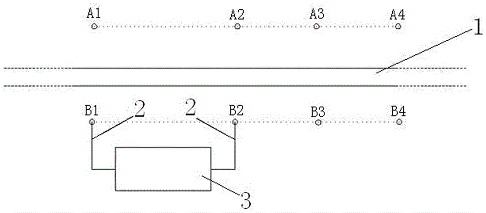
[0017] Embodiment one: if figure 1 As shown, the underground diaphragm wall 1 is set in the foundation pit (the foundation pit is not shown). This embodiment is used to detect whether there is leakage on the wall of the underground diaphragm wall and the location and range of the leakage point.

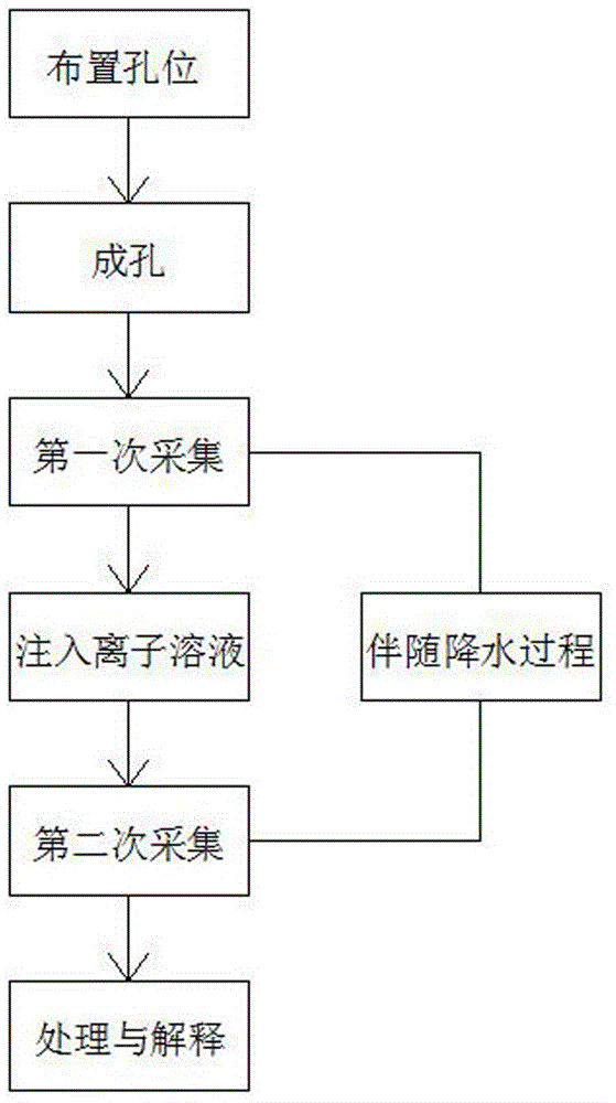
[0018] The leakage detection method of underground diaphragm wall 1 in the present embodiment comprises the following steps:

[0019] 1) Layout hole position: such as figure 1 As shown, test holes A1-A4 and test holes B1-B4 are set up on the inner and outer sides of the foundation pit and within a certain range from both sides of the underground diaphragm wall 1 . The test holes A1-A4 and B1-B4 on the inner and outer sides of the foundation pit should be 1-2m away from the underground diaphragm wall respectively. effective detection. The connection line of the test hole A1-A4 and the connection line of the test hole B1-B4 are kept parallel to the underground diaphragm wall 1, and t...

Embodiment 2

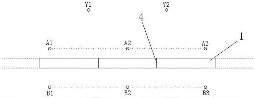
[0024] Embodiment 2: Compared with Embodiment 1, this embodiment differs in that: figure 2 As shown, ion solution injection holes Y1 and Y2 are opened outside the foundation pit, and the ion solution injection holes Y1-Y2 are located outside the test holes A1-A3 outside the underground diaphragm wall 1 . Such as image 3 As shown, after the first detection work is completed, low-resistance ion solutions of appropriate concentrations are injected into the ion solution injection holes Y1 and Y2 respectively. Due to the difference in water pressure, the groundwater outside the foundation pit will flow into the foundation pit. If there is leakage in the underground diaphragm wall 1, the low-resistance ion solution injected into the ion solution injection holes Y1 and Y2 outside the foundation pit will pass through the seepage of the underground diaphragm wall 1. Leaks flow to the inside of the foundation pit. Then in "data processing and judgment", the resistivity profile detec...


PUM


Abstract

The invention relates to the field of geotechnical engineering detection and test, in particular to an underground continuous wall leakage detection method. The method is characterized in that the inner side and the outer side of an underground continuous wall are each provided with multiple test holes; resistivity detection is conducted on two adjacent test holes in the same side in sequence before and after foundation pit dewatering, and the resistivity profiles between the two adjacent test holes are worked out according to the detection result; the resistivity profiles of the same position before and after foundation pit dewatering are compared, if it is found that low-resistance abnormality exists in the resistivity profile after foundation pit dewatering compared with the resistivity profile before foundation pit dewatering, it is judged that leakage occurs to the position, corresponding to the low-resistance abnormal resistivity profile, of the underground continuous wall. The underground continuous wall leakage detection method has the beneficial effects that the amount of collected data is large, the detection resolution ratio is high, sensitivity to the resistivity difference is high, and a good effect is achieved on the aspect of ground wall leakage detection; and leakage detection can be conducted on a certain segment of the underground continuous wall at a time, and meanwhile, no influence on the structural body of the underground continuous wall is generated.

Description

technical field [0001] The invention relates to the field of geotechnical engineering detection and testing, in particular to an underground diaphragm wall leakage detection method. Background technique [0002] With the rapid development of urban underground space construction, there are more and more foundation pit projects. Not only the area of ​​foundation pits is gradually increasing, but also the excavation depth of foundation pits is getting deeper and deeper. As a deep foundation pit with good comprehensive performance, the underground diaphragm wall The enclosure structure has been widely used. Restricted by factors such as the construction technology of the underground diaphragm wall, the joint form, and the influence of the stratum environment, the possibility of hidden leakage in the wall increases, which seriously threatens the construction safety of the foundation pit. In recent years, with the continuous launch of various large-scale foundation pit constructi...

Claims


Application Information

Patent Timeline
Patent Type & Authority Patents(China)
IPC IPC(8): E02D33/00
Inventor 黄永进马文亮胡绕唐坚朱黎明王水强殷习容贾兆磊李风生吴锋何伟
Owner SHANGHAI GEOTECHN INVESTIGATIONS & DESIGN INST
Why Eureka
Try Eureka