A quick locking device

A locking device, a fast technology, applied in the direction of fixtures, mechanical equipment, etc., can solve the problems of economic cost saving, labor cost and time cost advantages are not obvious, the number of components of the device is large, and it cannot be applied to actual needs. The effect of utilizing, improving assembly efficiency and saving assembly time

Active Publication Date: 2017-05-10
BEIJING RES INST OF PRECISE MECHATRONICS CONTROLS +1
View PDF5 Cites 0 Cited by
  • Summary
  • Abstract
  • Description
  • Claims
  • Application Information

AI Technical Summary

Problems solved by technology

[0004] Comprehensively analyzing the above inventions, the common problems are that the structure is relatively complex, the number of device components is large, and the operation is cumbersome. Disassembly, the advantages in saving economic costs, labor costs and time costs are not obvious enough, and cannot be applied to actual needs

Method used


Image

  • A quick locking device
  • A quick locking device
  • A quick locking device

Examples


Embodiment Construction

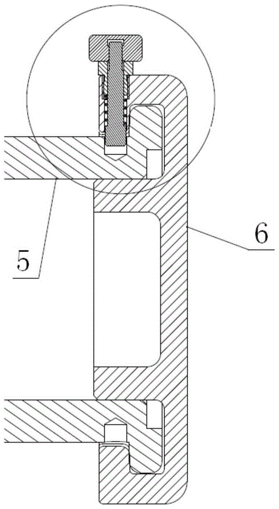
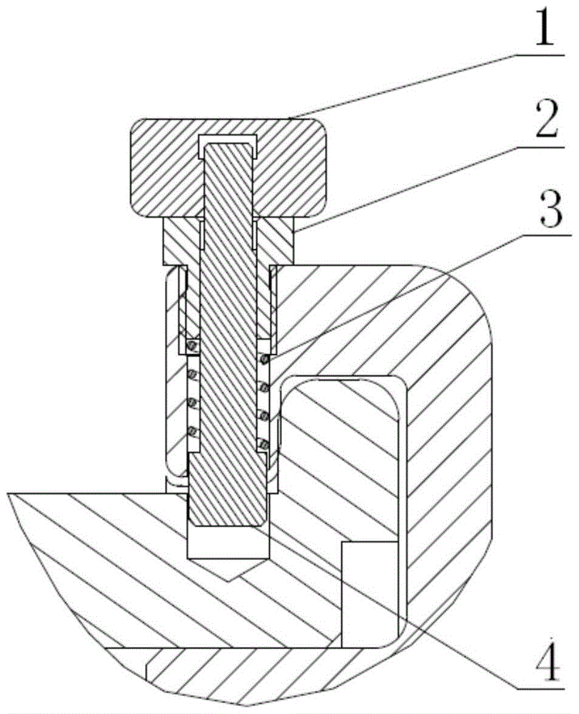
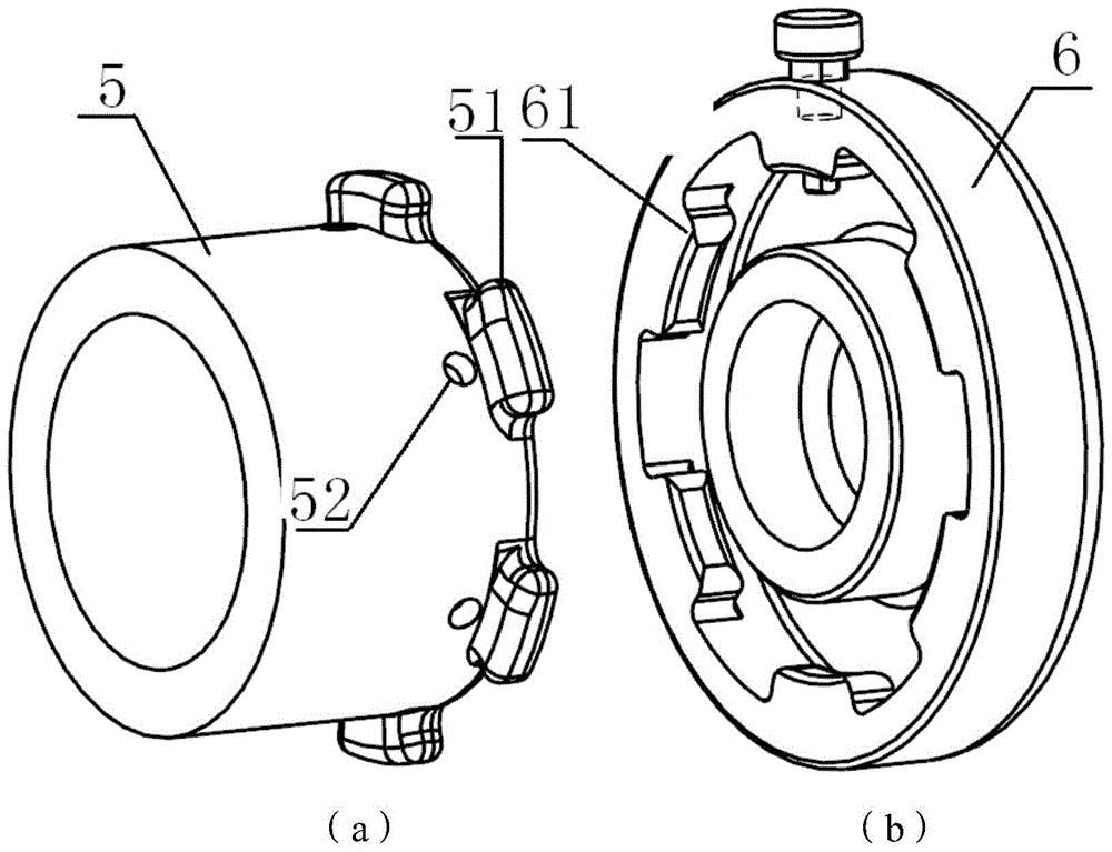
[0025] The present invention provides a fast clamping locking device, comprising: a nut 1 , a screw sleeve 2 , a spring 3 , a locking pin 4 , a first clamping opening 61 , and a second clamping opening 51 . Such as Figure 4 As shown, the nut 1 is cylindrical, and there is a mounting hole in the center of the cylindrical shape; as Figure 5 As shown, the locking pin 4 includes three sections of cylinders. The surface of the cylinder at one end is processed with threads, and the two sides of the cylinder at the other end are cut out by two planes parallel to the symmetry axis of the locking pin 4. Two symmetrical planes are cut out. The three sections of cylinders directly from the threaded end to increase sequentially; for example Image 6 , Figure 7 As shown, the screw sleeve 2 includes two cylinders with different diameters, the outer surface of the smaller diameter cylinder is processed with threads, and the center of the screw sleeve 2 has a through hole, which runs thr...


PUM


Abstract

The invention provides a fast clamping locking device which comprises nuts (1), thread sleeves (2), springs (3), locking pins (4), first clamping supporting rims (61) and second clamping supporting rims (51). One end of each locking pin (4) is fixedly connected with the corresponding nut (1), and the other end of each locking pin (4) is inserted in a locking blind hole (52). Each locking pin (4) is sleeved with the corresponding thread sleeve (2). Each thread sleeve (2) is mounted in a mounting hole of an end cover (6). Each locking pin (4) is sleeved with the corresponding spring (3). One end of each spring (3) is connected with the corresponding thread sleeve (2), and the other end of each spring (3) is connected with the end, inserted in the corresponding locking blind hole (52), of the corresponding locking pin (4). The nuts (1) are pulled out or loosened, the springs (3) are driven to stretch out and draw back, the locking pins (4) are made to move in the mounting holes of the end cover (6), and therefore mounting, dismounting and locking of the end cover (6) and a shell (5) are achieved. Through the fast clamping locking device, high-precision and high-reliability connection between structures is achieved in a narrow space; the fast clamping locking device is compact in structure, easy to operate, capable of being dismounted and mounted repeatedly and good in maintainability.

Description

technical field [0001] The invention relates to a snap-fit ​​locking device. Background technique [0002] The aerospace hydrogen gas engine is the core power component of the rocket, which undertakes the function of energy conversion. Its internal blades are made of carbon cloth fiber composite materials that are particularly sensitive to humidity. During the test and use, there is a process of repeated installation and disassembly between the shell and the end cover, and the operation is required to be completed instantaneously, so as to avoid potential safety hazards caused by the degradation of the internal blade's moisture performance or hydrogen leakage, which requires high connection speed and reliability. ; The operating space is extremely narrow, and tooling tools such as wrenches and screwdrivers cannot be used, and the requirements for the simplicity of operation are relatively high. Mechanical snap-fit ​​locking devices are widely used in the mechanical field. W...

Claims


Application Information

Patent Timeline
Patent Type & Authority Patents(China)
IPC IPC(8): F16B1/02
Inventor 王书武李冀鹏胡小飞朱熠
Owner BEIJING RES INST OF PRECISE MECHATRONICS CONTROLS
Why Eureka
Try Eureka