Connector structure used for dual-table synchronous vibration

A synchronous vibration and connector technology, applied in vibration testing, machine/structural component testing, measuring devices, etc., can solve the problems of reducing the fidelity of the test, unable to stand upright, damage to the shaking table body, etc., and achieve high efficiency in the testing process. Fast, simple structure, eliminates the effect of lateral pulling force

Active Publication Date: 2016-01-13
SUZHOU SUSHI TESTING INSTR CO LTD
View PDF11 Cites 3 Cited by
  • Summary
  • Abstract
  • Description
  • Claims
  • Application Information

AI Technical Summary

Problems solved by technology

The above-mentioned structure has the following defects: since the load-carrying capacity of the elastic connector 32 and the structural rigidity are a pair of contradictions, it is difficult to meet the requirements of the two aspects, and there is a certain amount of lateral pull on the long test piece 5 in the length direction of the vibrating table body. The force will cause some damage to the vibrating table body
However, since the two connectors are double-spherical hinge connectors 41, they can fall to either side within the spherical angle, resulting in the defect of being unable to stand upright.
Generally, the user uses one or two elastic tension ropes 42 to hang the long test piece 5 during the test to reduce the annoying vibration of random swing, and superimpose many components in other directions on the standard vertical vibration. Reduced the fidelity of the test; Sometimes the suspension frame 43 of the elastic tension rope 42 must be temporarily supported, which increases the extra workload

Method used


Image

  • Connector structure used for dual-table synchronous vibration
  • Connector structure used for dual-table synchronous vibration
  • Connector structure used for dual-table synchronous vibration

Examples


Embodiment 1

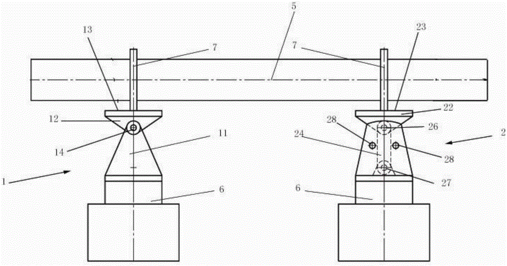
[0035] See attached image 3 As shown, a joint structure for double-stage synchronous vibration includes a single-hinge joint 1 and a double-hinge joint 2, wherein:

[0036] The single hinge connector 1 includes a first base 11 and a first work surface 12 , the first work surface 12 has a first bearing plane 13 , and the first work surface 12 is connected to the first base 11 through a first hinge 14 .

[0037] The double hinge connector 2 includes a second base 21, a connecting rod 24 and a second work surface 22, the second work surface 22 has a second bearing plane 23, and the second work surface 22 is connected to the second base through the connecting rod 24 21, the second base 21 has two side walls 25 facing each other at intervals, the connecting rod 24 is arranged between the two side walls 25, and the upper end of the connecting rod 24 is connected to the second work surface 22 through the second hinge 26 , the lower end of the connecting rod 24 is connected to the b...

Embodiment 2

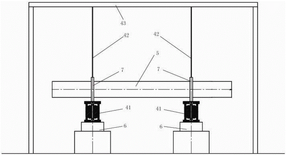
[0042] See attached Figure 4 As shown, the difference between this embodiment and Embodiment 1 is: a joint structure for double-stage synchronous vibration, including a pair of double-hinge joints 2;

[0043] The double hinge joint 2 includes a second base 21, a connecting rod 24 and a second work surface 22, the second work surface 22 has a second bearing plane 23, and the second work surface 22 connects the second work surface 22 through the connecting rod 24 and the second work surface 22. The bottom of the base 21 is connected, and the second base 21 has two side walls 25 facing each other at intervals. connected, the lower end of the connecting rod 24 is connected to the bottom of the second base 21 through the third hinge 27, and the second hinge 26 is arranged parallel to the axis of the third hinge 27; A limiting structure is provided on the side to limit the swing angle of the connecting rod 24 .

[0044] In the state of use, the second hinges 26 of the two double-hi...


PUM


Abstract

The invention provides a connector structure used for dual-table synchronous vibration, which is characterized by comprising a single hinge connector and a dual-hinge connector which are used in a matched manner or two dual-hinge connectors used in pairs, wherein the single hinge connector comprises a first base and a first working table board, the first working table board comprises a first bearing plane, and the first working table board is connected with the first base through a first hinge; the dual-hinge connector comprises a second base, a connecting rod and a second working table board, the working table board comprises a second bearing plane and is connected with the bottom part of the second base through the connecting rod, the second base comprises two side walls which are spaced in a face-to-face manner, the connecting rod is arranged between the two side walls, the upper end of the connecting rod is connected with the second working table board through the second hinge, the lower end of the connecting rod is connected with the bottom part of the second base through a third hinge, and axes of the second hinge and the third hinge are parallelly arranged; and limiting structures are arranged on both sides of the connecting rod on a swinging plane of the connecting rod for limiting swinging angle of the connecting rod.

Description

technical field [0001] The invention relates to the field of environmental mechanics test equipment, in particular to a connector structure for double-stage synchronous vibration tests of slender rods. Background technique [0002] Mechanical environment test—vibration test is mainly used to simulate the environment where the product is subjected to vibration during use, loading and unloading and transportation, so as to determine the adaptability of the product to various vibrations. Through such a vibration test, the integrity of a product structure and the rationality of the working performance index parameters can be assessed, providing a reasonable basis for assessing the quality of the product. Vibration testing is commonly used in precision products such as aerospace, but also in automotive components and instrumentation electronics. [0003] For the vibration test of slender rods, due to the limitation of the table surface of the vibration table, the double-table pa...

Claims


Application Information

Patent Timeline
Patent Type & Authority Applications(China)
IPC IPC(8): G01M7/02
Inventor 胡新华钟琼华
Owner SUZHOU SUSHI TESTING INSTR CO LTD
Why Eureka
Try Eureka