pneumatic tire

A technology for pneumatic tires and tires, applied in tire parts, tire sidewalls, transportation and packaging, etc., can solve problems such as obstruction of air flow, poor durability, and easy to become cracks, to prevent vulcanization failures and improve crack resistance. performance, the effect of preventing local concentration of air

Inactive Publication Date: 2017-06-06
THE YOKOHAMA RUBBER CO LTD
View PDF7 Cites 0 Cited by
  • Summary
  • Abstract
  • Description
  • Claims
  • Application Information

AI Technical Summary

Problems solved by technology

[0004] However, if circumferential ribs and radial ribs are formed as described above, these ribs may obstruct air flow during tire building, and vulcanization failure may occur
In addition, since the plurality of intersections formed by intersecting the circumferential ribs and the radial ribs tend to be the starting point of cracks, there is a problem that the durability of the decoration itself deteriorates.

Method used


Image

  • pneumatic tire
  • pneumatic tire
  • pneumatic tire

Examples


Embodiment

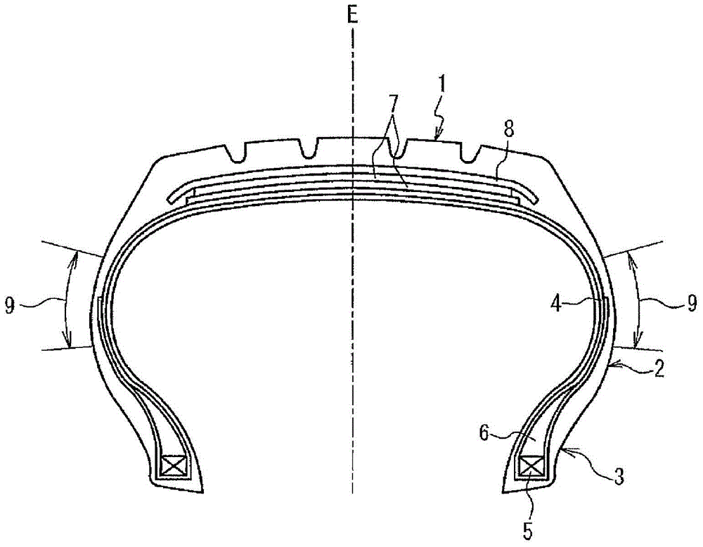
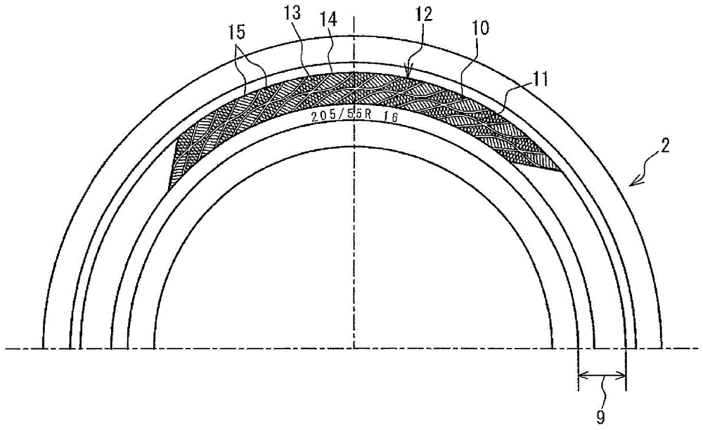
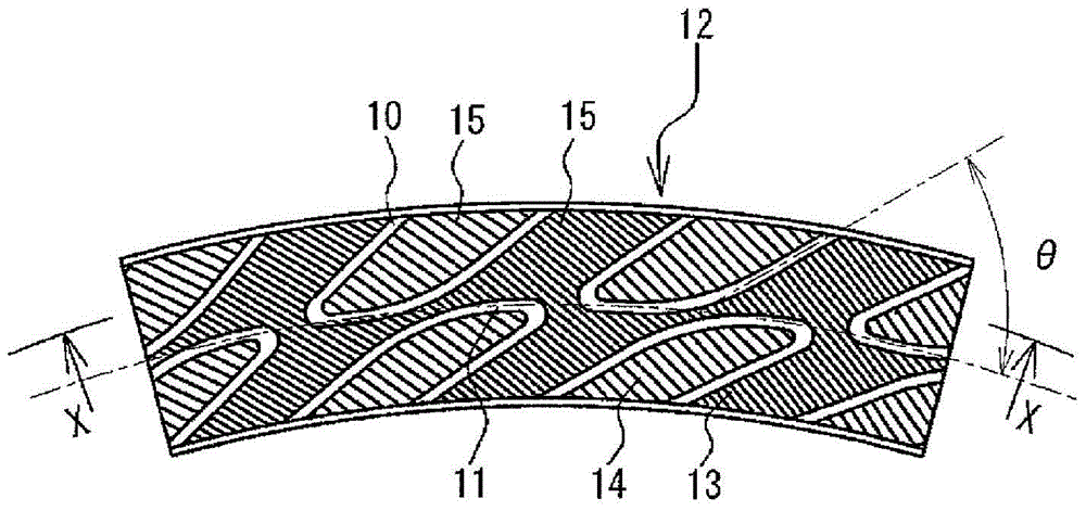
[0055] The tire size is 205 / 55R16, with figure 1 The cross-sectional shape shown, the decorative part structure provided on the side wall part, that is, the angle of the linear part of the radial and circumferential ribs, the shape of the circumferential rib, the width of the radial and circumferential ribs, The shape of the connecting portion, the respective shapes of the first region and the second region, the ratio of the total area, the ridge density, and the ratio of the ridge density of the first region to the second region are respectively shown in Table 1. Conventional example 1, comparison Examples 1 to 3 and Examples 1 to 8 total 12 kinds of pneumatic tires.

[0056] In addition, the ratio of the total area of ​​each region refers to the ratio of the total area of ​​each region to the area of ​​the entire decorative part. The ratio of the ridge density refers to the ratio of the ridge density in the region with relatively large ridge density to the ridge density in ...


PUM


Abstract

A pneumatic tire includes a decorative portion on an outer surface of a side wall portion that includes a first region that is linked to the inner side in the tire radial direction and the outer side in the tire radial direction of the decorative portion without being divided by a circumferential direction rib band, and a second region that is continuously surrounded in at least three directions by a radial direction rib band and the circumferential direction rib band, the total area of the first region and the total area of the second region are each 10% or greater of the total area of the decorative portion, ridges are provided in at least one of the first region and the second region, and the pattern contrast between the first region and the second region is varied.

Description

technical field [0001] The present invention relates to a pneumatic tire having a decorative portion on a sidewall portion, and more particularly, to a pneumatic tire capable of preventing failures in the manufacture of the tire due to the installation of the decoration and improving the decoration while maintaining excellent concealment performance. Durable pneumatic tires. Background technique [0002] Generally, in a pneumatic tire, irregularities are generated on the outer surface of the sidewall portion due to the structure of the tire member. For example, at the joint portion or the rolled-up end of the carcass, between the ends of the sheets constituting the carcass or when the main body of the carcass and the rolled-up part are laminated, the thickness becomes substantially two layers. Concavities and convexities are generated on the outer surface of the wall portion. [0003] In contrast, generally, a decorative portion is provided on the side wall portion so as t...

Claims


Application Information

Patent Timeline
Patent Type & Authority Patents(China)
IPC IPC(8): B60C13/00B60C13/02
Inventor 村田尚久
Owner THE YOKOHAMA RUBBER CO LTD
Why Eureka
Try Eureka