Plasma jet spark plug

a spark plug and jet technology, applied in the direction of spark plugs, machines/engines, mechanical equipment, etc., can solve the problems of rapid increase of the voltage required for spark discharge, broken insulation between the central electrode and the ground electrode, and the central electrode, so as to achieve the effect of preventing local concentration of channeling

Active Publication Date: 2011-09-08
NGK SPARK PLUG CO LTD
View PDF5 Cites 2 Cited by
  • Summary
  • Abstract
  • Description
  • Claims
  • Application Information

AI Technical Summary

Benefits of technology

[0011]Hereinafter, each component suitable for accomplishing the above advantage will be described claim by claim. Also, characteristic operation effects of the corresponding component will be described as necessary.
[0013]In accordance with the present invention, there is provided 1. A plasma jet spark plug, comprising:
[0014]a cylindrical insulator having an axial bore extending therethrough in an axial direction;
[0015]a rod-shaped central electrode inserted into the axial bore so that a front end surface of the central electrode is located further to the rear end side in the axial direction than the front end of the insulator;
[0016]a cylindrical metal shell disposed around an outer peripheral surface of the insulator;
[0024]According to the configuration 1, at an initial stage (before the central electrode or the like is not consumed), the cavity portion has a cylindrical shape formed by the sidewall section extending along the axis line with a straight shape and the front end surface of the central electrode. For this reason, local concentration of channeling may be more reliably prevented, compared with the case where the inner peripheral surface of the cavity portion is formed into a stepped shape.

Problems solved by technology

First, a voltage is applied between the central electrode and the ground electrode to cause a spark discharge between them, so that the insulation between the central electrode and the ground electrode is broken.
However, if high-energy current flows in, the central electrode is easily consumed, and thus the voltage required for the spark discharge (the voltage demanded) may be rapidly increased.
However, the insulator located at the spark discharge path is worn thin due to the spark discharge (this phenomenon is referred to as, so-called, channeling).
Also, in the spark discharge path, a path passing the worn region of the insulator becomes shorter than other paths, and thus spark discharge is focused in the path, which results in local concentration of the channeling.
Even though spark discharge and generation of plasma is caused along the groove, the plasma may not be easily jetted out of the cavity portion due to the presence of the ground electrode or the like.
In other words, according to the technique disclosed in the patent document JP-A-2007-287666, although excellent ignition quality is realized at an initial stage, the rapid deterioration of ignition quality may accompany use.
For this reason, the heat dissipation of the central electrode is extremely deteriorated, and thus the central electrode may be rapidly consumed.

Method used


Image

  • Plasma jet spark plug
  • Plasma jet spark plug
  • Plasma jet spark plug

Examples


Embodiment Construction

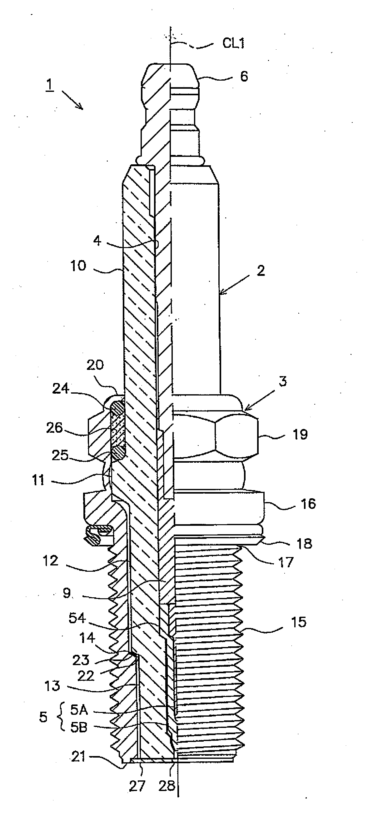
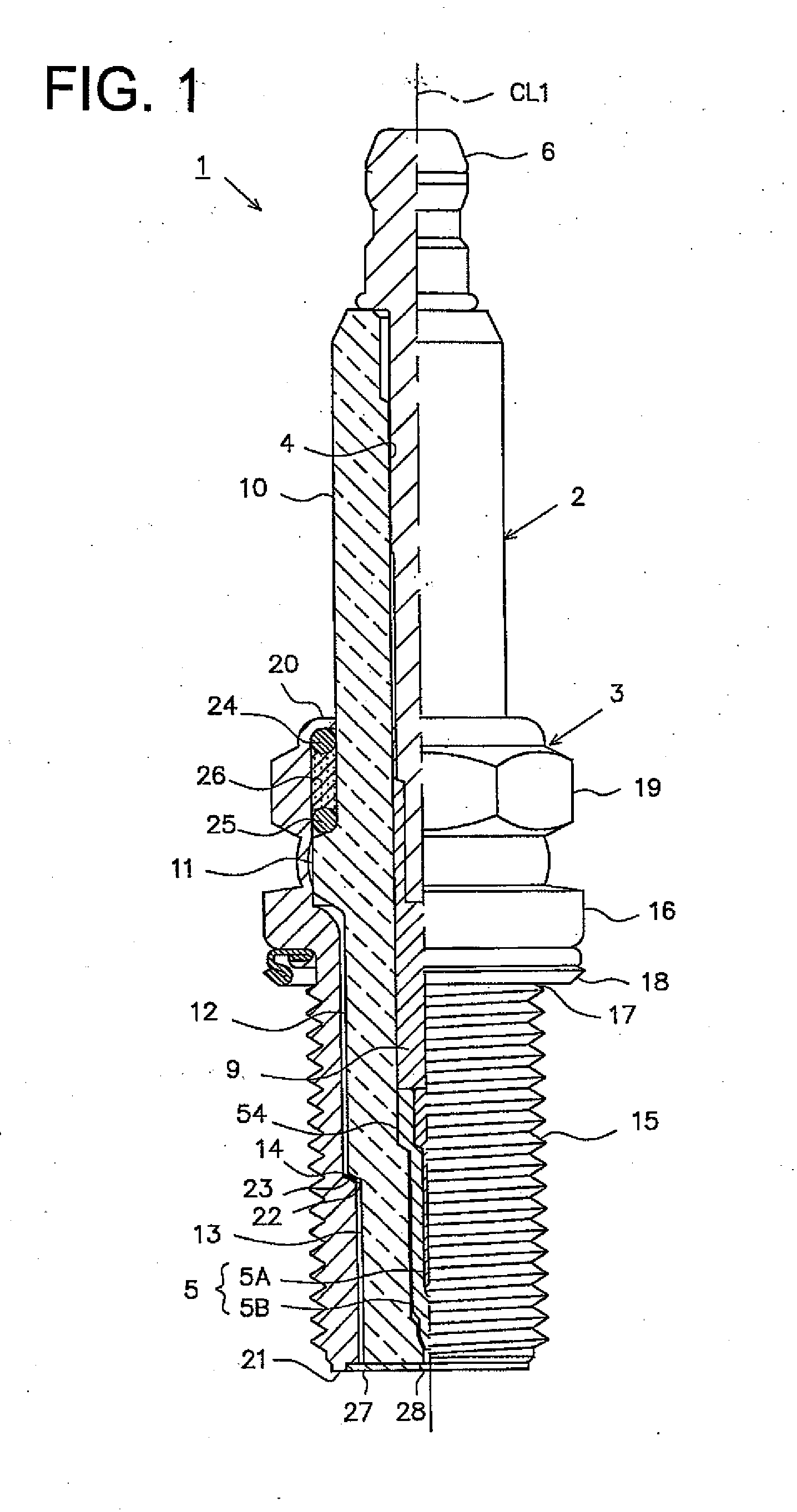
[0055]Hereinafter, one embodiment will be described with reference to the drawings. FIG. 1 is a partially-sectioned front view showing a plasma jet spark plug (hereinafter, referred to as a “spark plug”) 1. In FIG. 1, the direction of an axis line CL1 of a spark plug 1 is assumed to be the vertical direction, wherein a lower side is a front end side of the spark plug 1 and an upper side is a rear end side of the spark plug 1.

[0056]The spark plug 1 includes an insulator 2 that is a cylindrical insulating body, and a cylindrical metal shell 3 supporting the insulator 2.

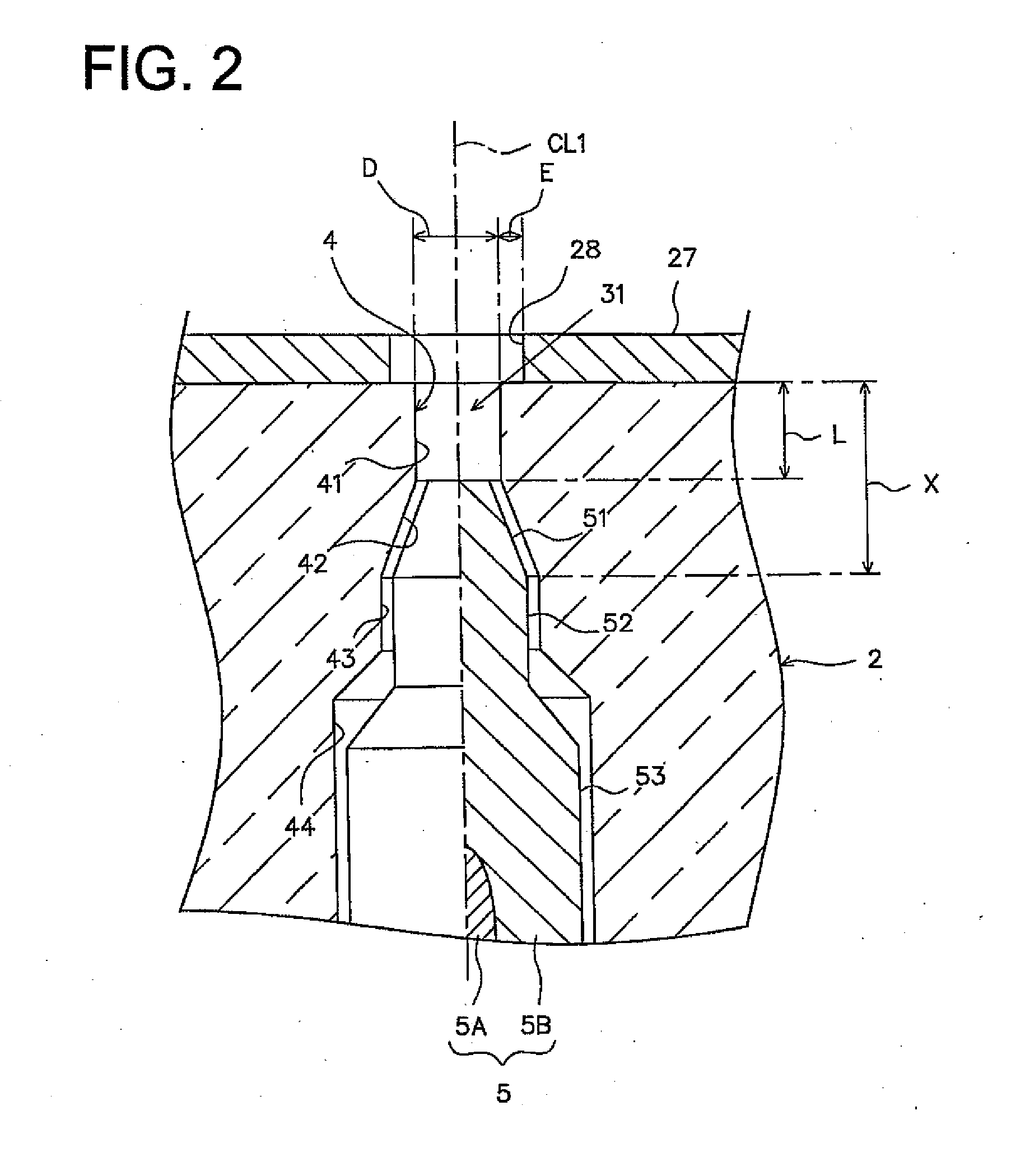
[0057]The insulator 2 is formed by firing alumina or the like as well known in the art. In its appearance, the insulator 2 includes a rear end side chamber 10 formed at a rear end side thereof. A large-diameter region 11 protrudes outwards in a radial direction at a further front end side to the rear end side chamber 10. A middle chamber 12 is formed at a further end side to the large-diameter region 11 and has a smalle...


PUM


Abstract

A plasma jet spark plug for igniting an air-fuel mixture in a conventional combustion device such as an internal combustion engine.

Description

FIELD OF THE INVENTION [0001]The present invention relates to a plasma jet spark plug for igniting an air-fuel mixture by forming plasma.BACKGROUND OF THE INVENTION[0002]In a conventional combustion device such as an internal combustion engine, a spark plug for igniting an air-fuel mixture by spark discharge is used. Recently, in order to cope with the demands for higher output and higher fuel efficiency of combustion devices, a plasma jet spark plug was proposed as a spark plug capable of more reliably igniting even a lean air-fuel mixture with fast combustion spreading and an air-fuel ratio higher than ignition limit air-fuel ratio.[0003]Generally, a plasma jet spark plug includes a cylindrical insulator having an axial bore, a central electrode inserted into the axial bore so that the front end surface thereof is inserted further than the front end surface of the insulator, a metal shell disposed at the outer peripheral surface of the insulator, and an annular ground electrode jo...

Claims


Application Information

Patent Timeline
Patent Type & Authority Applications(United States)
IPC IPC(8): H01T13/20
CPCH01T13/50F02P9/007
Inventor KAMEDA, HIROYUKISATO, YOSHIKUNINAKANO, DAISUKEYAMAMURA, NAOFUMIKASAHARA, DAISUKE
Owner NGK SPARK PLUG CO LTD
Why Eureka
Try Eureka