Ceramic heater and manufacturing method for tubular shaft

Active Publication Date: 2020-03-05
NGK INSULATORS LTD
View PDF0 Cites 1 Cited by
  • Summary
  • Abstract
  • Description
  • Claims
  • Application Information

AI Technical Summary

Benefits of technology

The present invention aims to prevent high temperatures at the lower end of a tubular shaft and maintain a good external appearance for a long period. The invention provides a through-hole structure that allows for a long path of heat transfer and reduces temperature differences between different parts of the plate. The tubular shaft has a vertical sectional shape with an S-like portion or curved portion, and the through-hole is a gas path or a tubular space between the inner and outer circumferential walls of the tubular shaft. The use of a gas flow hole or vacuum suction hole makes it easy to supply or evacuate gas, improving thermal uniformity and preventing damage to the tubular shaft. The manufacturing method is easy to implement even for tubular shafts with complex shapes.

Problems solved by technology

Therefore, a high increase in temperature at a lower end surface of the tubular shaft is unavoidable.
If the temperature at the lower end surface of the tubular shaft becomes too high, there is a possibility that the surface temperature may exceed the heat resistance temperature of an O-ring, and that the O-ring may no longer exhibit sufficient sealing performance.
Furthermore, in PTL 1, because the insertion path has the structure in which the recessed groove is covered with the lid member, an external appearance is not so good, and detachment of the lid member may occur if the joining of the lid member is insufficient.

Method used


Image

  • Ceramic heater and manufacturing method for tubular shaft
  • Ceramic heater and manufacturing method for tubular shaft
  • Ceramic heater and manufacturing method for tubular shaft

Examples


Embodiment Construction

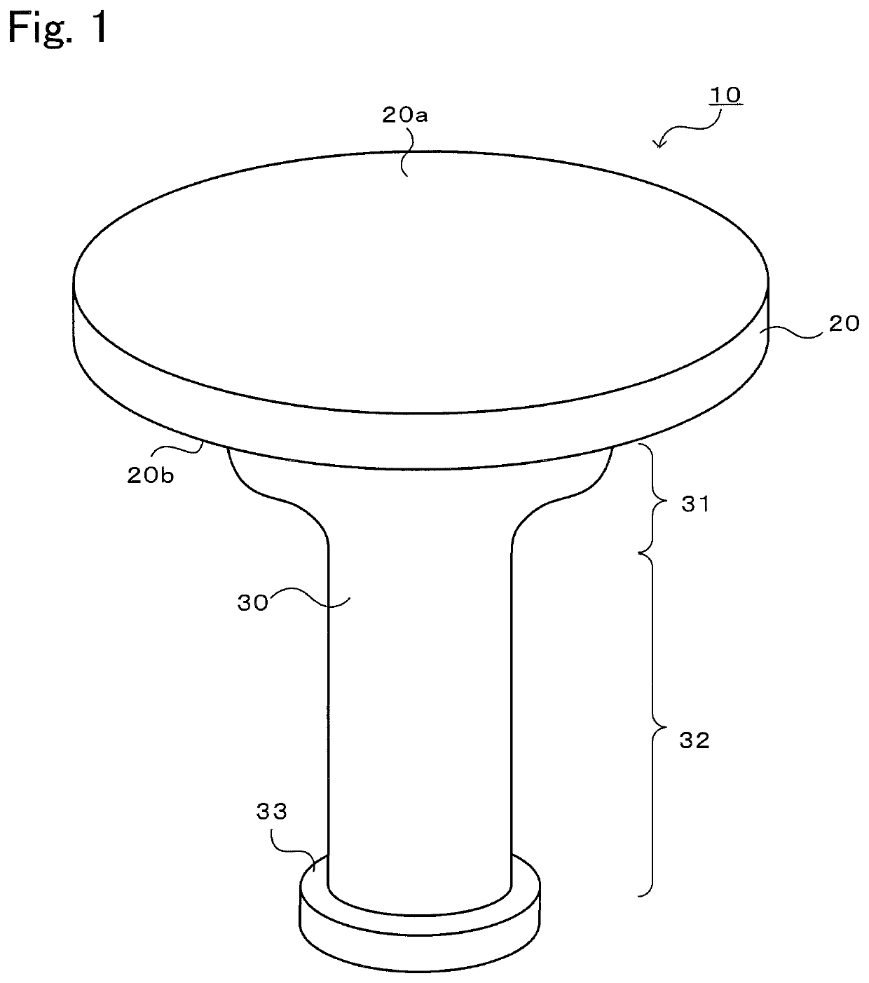
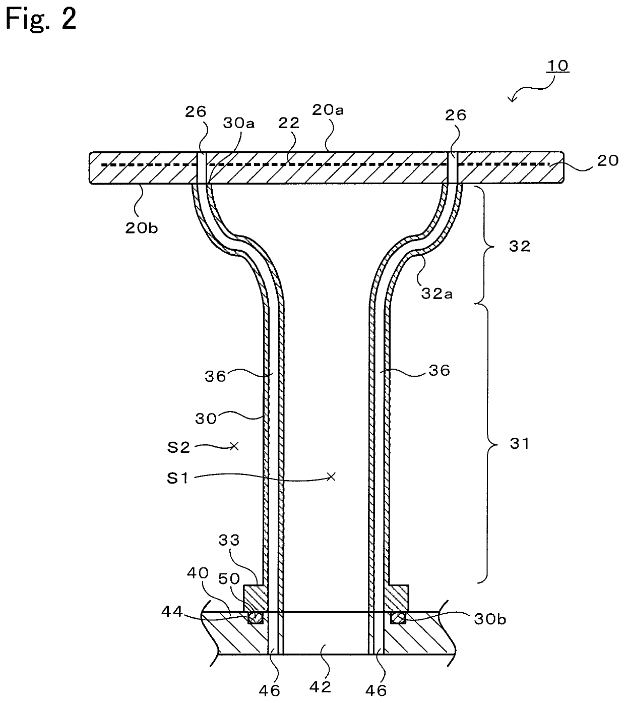
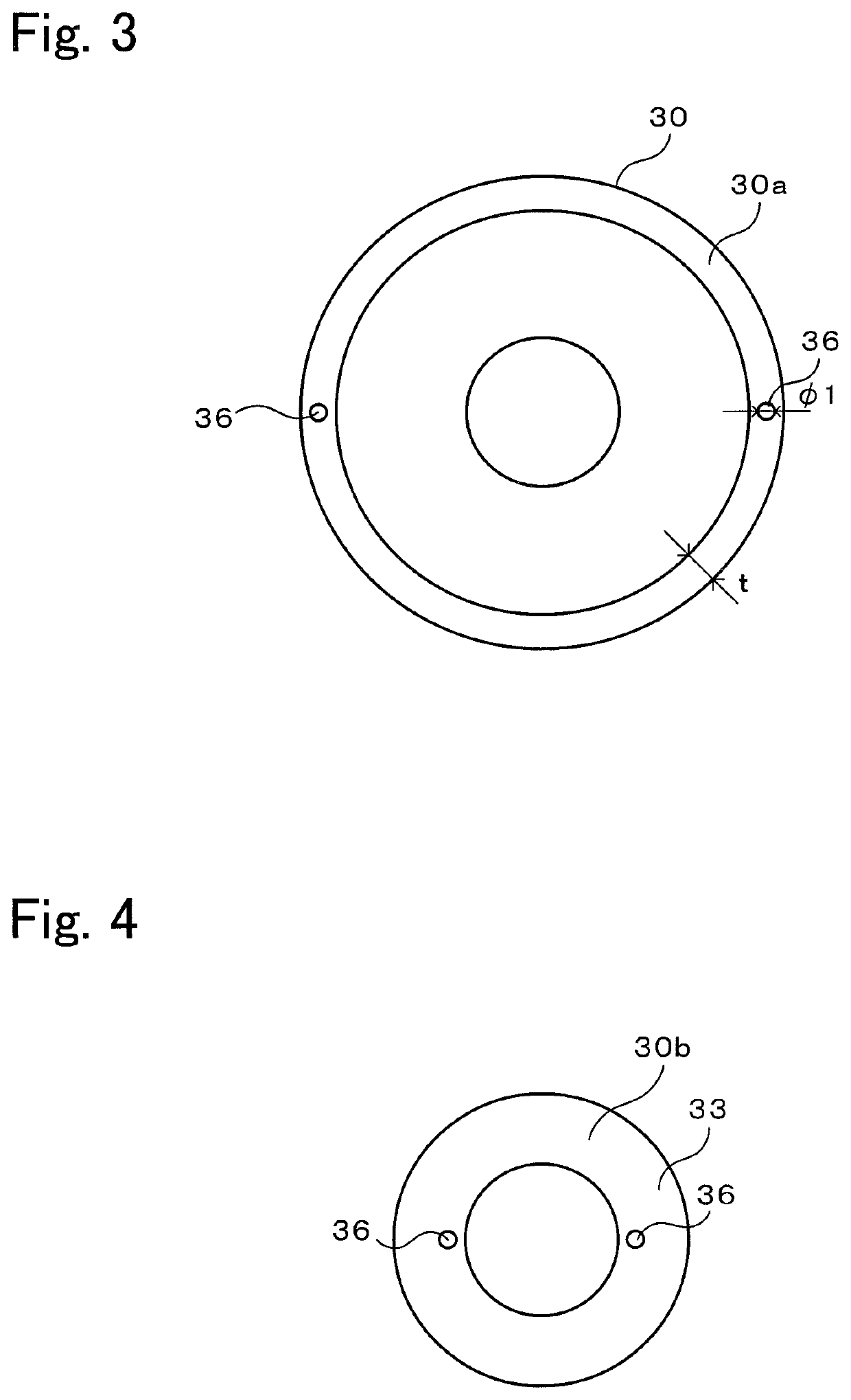
[0026]The preferred embodiments of the present invention will be described below with reference to the drawings. FIG. 1 is a perspective view of a ceramic heater 10, and FIG. 2 is a vertical sectional view of the ceramic heater 10 (i.e., a sectional view when the ceramic heater 10 is sectioned along a plane including a center axis). FIG. 3 is a plan view of a tubular shaft 30, and FIG. 4 is a bottom view of the tubular shaft 30.

[0027]The ceramic heater 10 is used to heat a wafer on which processing such as etching or CVD is to be performed, and is installed within a not-illustrated vacuum chamber. The ceramic heater 10 includes a plate 20 on which the wafer can be placed, and a tubular shaft 30 supporting the plate 20.

[0028]The plate 20 is a ceramic disk in which a resistance heating element 22 is incorporated. The surface of the plate 20 serves as a wafer placement surface 20a on which the wafer is to be placed. A large number of fine columnar bosses (not illustrated) are formed on...


PUM


Abstract

A ceramic heater includes a ceramic plate having a wafer placement surface on which a wafer is to be placed, and incorporating a resistance heating element therein, and a ceramic tubular shaft having one end joined to a rear surface of the plate. The tubular shaft has a vertical sectional shape including an S-like portion or a curved portion having an inflection point in at least one position, and includes a through-hole penetrating the tubular shaft from the one end to the other end with an axis extending along the vertical sectional shape of the tubular shaft.

Description

BACKGROUND OF THE INVENTION1. Field of the Invention[0001]The present invention relates to a ceramic heater and a manufacturing method for a tubular shaft.2. Description of the Related Art[0002]There has hitherto been known a ceramic heater that includes a ceramic plate having a wafer placement surface on which a wafer is to be placed, the ceramic plate incorporating a resistance heating element therein, and a ceramic tubular shaft joined to a surface (rear surface) of the plate on the opposite side to the wafer placement surface. Patent Literature (PTL) 1 discloses a trumpet-shaped tubular shaft flaring upward, which is used in the above-mentioned type of ceramic heater. A lower end of the tubular shaft is attached to a base plate with an O-ring interposed between them. An insertion path through which a thermocouple is to be inserted is formed along a height direction in part of an outer wall of the tubular shaft. The insertion path is constituted by a recessed groove formed in an ...

Claims


Application Information

Patent Timeline
IPC IPC(8): H01L21/67H01L21/683H01J37/32H05B3/06H05B3/26
CPCH01L21/6838F27D5/0031H01J37/32724H05B3/06H05B3/265H01L21/67103H05B3/22H01L21/68792H01L21/67109H01L21/68785H01L21/68757H01L21/67248H01L21/683H01L21/4807
Inventor UNNO, YUTAKA
Owner NGK INSULATORS LTD
Why Eureka
Try Eureka