
Pipe welding fixture

A pipe fitting welding and fixture technology, applied in welding equipment, auxiliary welding equipment, welding/cutting auxiliary equipment, etc., can solve the problems of scrapped workpieces, difficult to dissipate heat quickly, and leakage of weld bead.

Pending Publication Date: 2020-10-23
FOSHAN OSCAR MEDICAL INSTR CO LTD
View PDF0 Cites 2 Cited by
  • Summary
  • Abstract
  • Description
  • Claims
  • Application Information

AI Technical Summary

Problems solved by technology

[0002] When welding the workpiece outside the pipe fitting or butt welding the pipe fitting, it is usually necessary to use a fixture to position the pipe fitting. The existing fixture usually clamps and fixes the pipe fitting outside the pipe fitting. During the welding process, due to the thinner pipe wall thickness of the workpiece , the high temperature at the weld bead causes heat concentration, and the heat is difficult to dissipate quickly, which leads to the occurrence of weld leakage and weld penetration in the weld bead, resulting in the scrapping of the workpiece

Method used


Image

  • Pipe welding fixture
  • Pipe welding fixture
  • Pipe welding fixture

Examples


Embodiment Construction

[0018] Below, in conjunction with accompanying drawing and specific embodiment, the present invention will be further described:

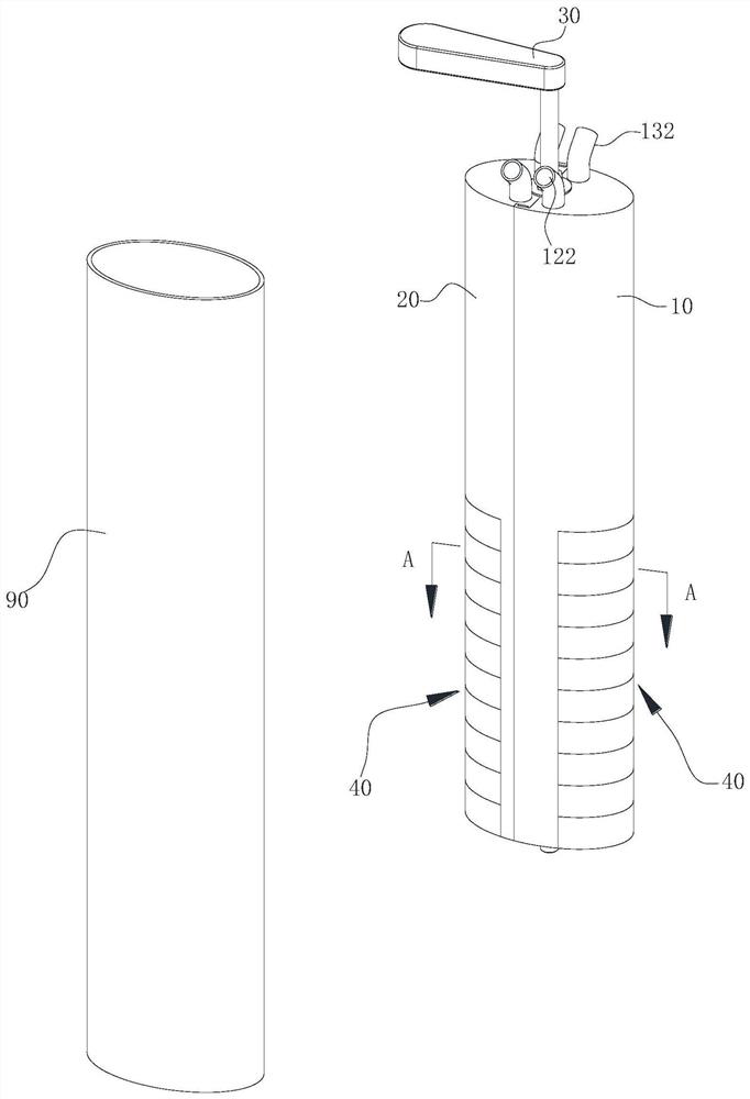
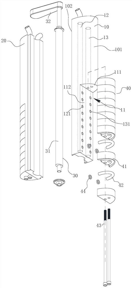
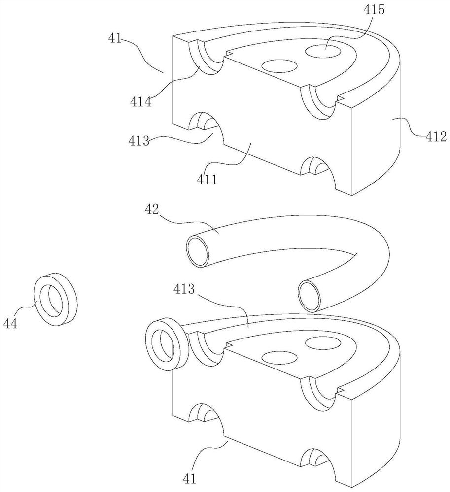
[0019] see figure 1 , 2 , 3, and 4 show a pipe fitting welding fixture of the present invention, which includes a mandrel 10, a mandrel 20, a spreader 30, and two heat-conducting members 40, wherein the mandrel 10 and the mandrel 20 are arranged oppositely and Inserted in the pipe 90, the spreader 30 is placed between the mandrel 10 and the mandrel 20, and the spreader 30 is used to push the mandrel 10 and the mandrel 20 toward the direction away from each other, so that the mandrel 10 The assembly with the mandrel 20 can be expanded to conform to the inner wall of the tube 90 . The structure of the mandrel 10 and the mandrel 20 is substantially the same, and the mandrel 10 is taken as an example below to illustrate its structure; the mandrel 10 includes a mating surface 102 on its inner side and a supporting surface 101 on its outer side, wherei...


PUM


Abstract

The invention relates to a pipe welding fixture. The pipe welding fixture comprises two core rods and an opening piece. The core rods comprise matching surfaces and supporting surfaces. The outer sides of the core rods are provided with concave positions. The concave positions comprise top walls and side walls. Two blind holes are formed in each core rod. Two columns of through holes are formed ineach side wall, wherein one column of the through holes communicates with one blind hole, and the other column of the through holes communicates with the other blind hole. Heat conduction members areembedded in the concave positions and comprise inner lateral sides and outer lateral sides. The inner lateral sides are attached to the side walls. The outer lateral sides are flush with the supporting surfaces of the core rods. A plurality of through holes are formed in the heat conduction members. One openings of the plurality of through holes are in one-to-one correspondence communication withone column of the through holes. The other openings of the plurality of through holes are in one-to-one correspondence communication with the other column of through holes. The top end of one blind hole communicates with the refrigerant output end of a cooling system, and the top end of the other blind hole communicates with the refrigerant return end of the cooling system. The pipe welding fixture can avoid the local concentration of heat in a pipe.

Description

technical field [0001] The invention relates to the field of welding technology, in particular to a pipe fitting welding jig. Background technique [0002] When welding the workpiece outside the pipe fitting or butt welding the pipe fitting, it is usually necessary to use a fixture to position the pipe fitting. The existing fixture usually clamps and fixes the pipe fitting outside the pipe fitting. During the welding process, due to the thinner pipe wall thickness of the workpiece , The high temperature at the weld bead causes heat concentration, and the heat is difficult to dissipate quickly, which leads to the occurrence of missing welding and welding penetration in the weld bead, resulting in the scrapping of the workpiece. Contents of the invention [0003] In view of the deficiencies in the prior art, the object of the present invention is to provide a pipe fitting welding jig, which can quickly dissipate the heat caused by welding, avoid heat concentration, and impro...

Claims


Application Information

Patent Timeline
Patent Type & Authority Applications(China)
IPC IPC(8): B23K37/053B23K37/00
CPCB23K37/00B23K37/003B23K37/053B23K37/0531
Inventor 罗耀球
Owner FOSHAN OSCAR MEDICAL INSTR CO LTD
Learn More