Method for solving welding deviation and welding equipment thereof

A technology of welding equipment and welding head, which is applied in the direction of welding equipment, auxiliary welding equipment, welding/cutting auxiliary equipment, etc. The effect of high bit rate

Pending Publication Date: 2020-07-31
DONGGUAN SANXIN PRECISION MACHINERY
View PDF0 Cites 5 Cited by
  • Summary
  • Abstract
  • Description
  • Claims
  • Application Information

AI Technical Summary

Problems solved by technology

[0004] In view of this, the present invention aims at the deficiencies in the prior art, and its main purpose is to provide a method for solving welding offset and its welding equipment, which can effectively solve the existing problem of welding based on the shape of the workpiece. Poor alignment rate and poor soldering yield

Method used


Image

  • Method for solving welding deviation and welding equipment thereof
  • Method for solving welding deviation and welding equipment thereof
  • Method for solving welding deviation and welding equipment thereof

Examples


Embodiment approach 1

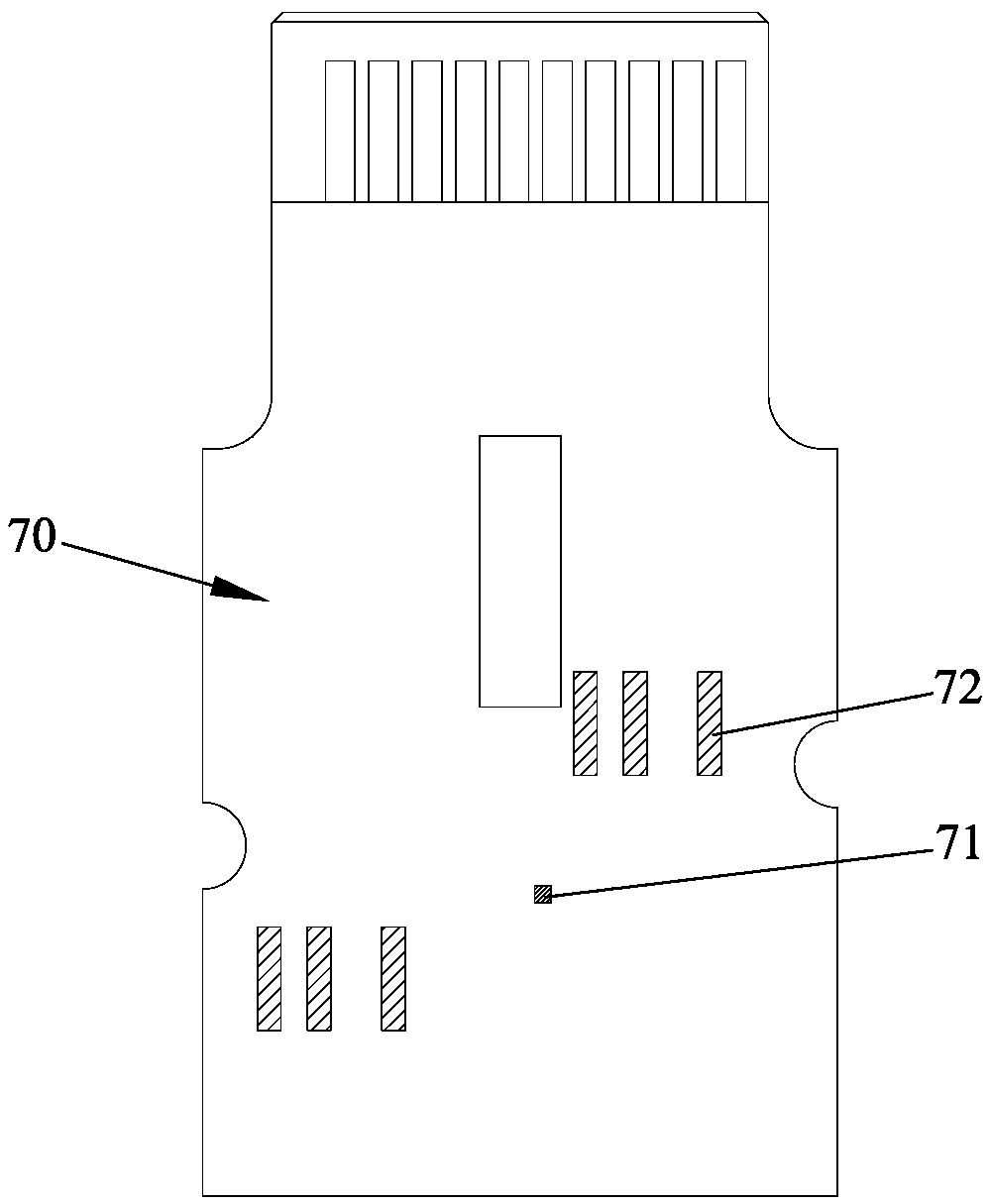
[0051] Embodiment 1: The image of the workpiece taken by the CCD device is displayed on the display screen, and it is judged whether the reference point A of the workpiece coincides with the standard reference point B stored in the CCD device; If they do not coincide, adjust the position deviation C displayed by the reference point B and the reference point A so that the reference point B coincides with the reference point A, and then translate the workpiece fixing device to the set distance to the position of the welding head. .

Embodiment approach 2

[0052] Embodiment 2: The image of the workpiece taken by the CCD device is displayed on the display screen, and it is judged whether the reference point A of the workpiece coincides with the standard reference point B stored in the CCD device; The position is enough; if they do not coincide, drive the workpiece fixing device to move through the conveying mobile device, so that the reference point B of the workpiece coincides with the reference point A;

Embodiment approach 3

[0053] Embodiment 3: The workpiece image captured by the CCD device is compared with the sample image stored on the display screen, the CCD device transmits the actual workpiece image to the control unit, and the control unit compares the actual workpiece image with the standard workpiece image, calculates the deviation value, and displays it on the display On the screen; the control unit automatically adjusts the welding head and the workpiece fixing device to compensate according to the deviation value, and moves the workpiece fixing device to the bottom of the welding station; and then performs welding.

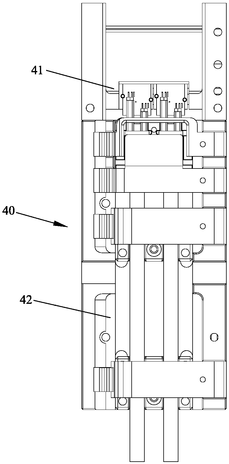
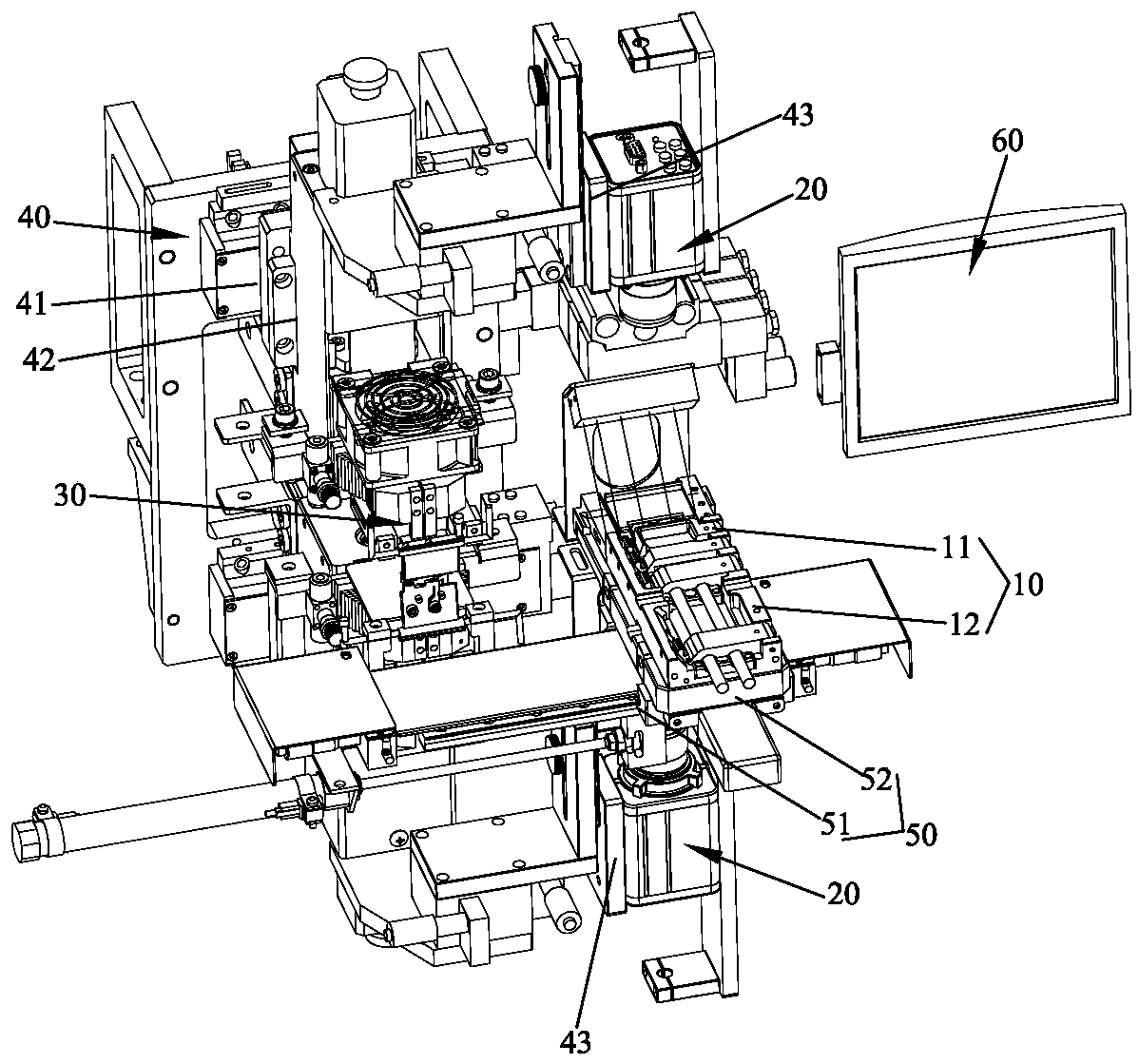
[0054] The welding equipment has a correction station and a welding station; the correction station is provided with a workpiece fixture 10, and above or below the workpiece fixture 10 is provided with a CCD device 20 for taking images of the workpiece; the welding station is provided with a welding head 30, the welding head 30 or the workpiece fixing device 10 is provided ...


PUM


Abstract

The invention discloses a method for solving welding deviation and welding equipment thereof. The method comprises the steps of employing a CCD device to shoot a workpiece image, and judging a position deviation value between an actual workpiece image and a standard workpiece image; if no position deviation exists, starting welding; and if the position deviation exists, compensating the position deviation value by moving a welding head or a workpiece fixing device, and then starting the welding. Therefore, the problem that deviation exists between a welding area of the workpiece and the welding head due to the fact that positioning is conducted through appearance of the workpiece traditionally can be effectively eradicated; and a high aligning rate of workpiece welding can be ensured, so that the welding yield of the workpiece is further improved.

Description

technical field [0001] The invention relates to the technology in the field of welding, in particular to a method for solving welding offset and welding equipment thereof. Background technique [0002] In the automobile, communication, medical, watch, mobile phone, computer and other industries, welding of precision parts is inseparable. Unlike ordinary parts, precision parts are more precise and have high requirements for precision. Laser welding has the characteristics of fast speed, large depth and small deformation. [0003] When the workpiece is welded, the workpiece is generally placed on the workpiece fixture, and then the workpiece is transported to the working position of the welding head for welding. Usually, when the workpiece is placed on the workpiece fixture, it is positioned according to the shape of the workpiece; when the workpiece is placed behind the workpiece fixture, there is a deviation between the welding area of ​​the workpiece and the working positi...

Claims


Application Information

Patent Timeline
Patent Type & Authority Applications(China)
IPC IPC(8): B23K37/02B23K37/04B23K37/00
CPCB23K37/00B23K37/0247B23K37/0252B23K37/0426
Inventor 姚天金
Owner DONGGUAN SANXIN PRECISION MACHINERY
Why Eureka
Try Eureka