
Discharging device

A cutting and lifting device technology, applied in stripping devices, metal processing, metal processing equipment, etc., can solve the problems of wasting energy, complex structure, affecting feeding, etc., and achieve the effect of ensuring continuity

Inactive Publication Date: 2016-01-20
天津市晟方庆宇科技发展有限公司
View PDF0 Cites 4 Cited by
  • Summary
  • Abstract
  • Description
  • Claims
  • Application Information

AI Technical Summary

Problems solved by technology

[0002] In the existing technology, after the steel pipe is processed, if it cannot be removed from the station in time, it will affect the subsequent feeding. Manual unloading will increase the labor intensity, and the steel pipe cannot be removed from the station in time and effectively, reducing the Processing efficiency, the existing automatic unloading device often needs to add a new driving device, the structure is complicated, and energy is wasted

Method used


Image

  • Discharging device
  • Discharging device
  • Discharging device

Examples


Embodiment Construction

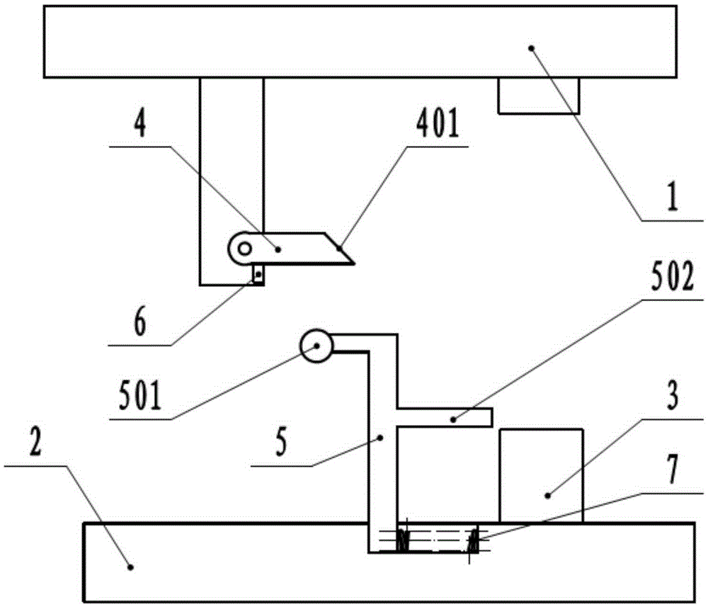
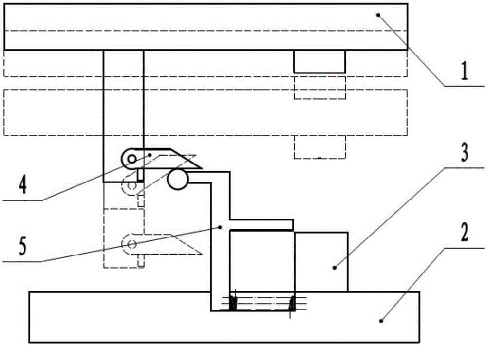
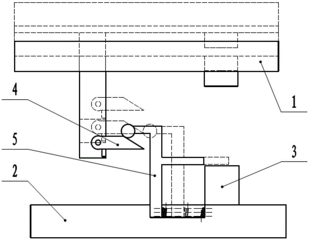
[0016] A blanking device includes a lifting device 1, a base 2, a workbench 3, a lever 4 and a discharge member 5; the base 2 is located below the lifting device 1; the workbench 3 is located between the lifting device 1 and the base 2, and Fixed connection; the driving rod 4 is horizontally arranged and connected to the lifting device 1 in rotation. The upper end of the driving rod 4 close to the discharge part 5 is provided with a transition surface 401, and the lower part of the driving rod 4 is provided with a stop block 6; the discharge part 5 is located at Between the lever 1 and the workbench 3, it is slidingly connected with the base 2, and an elastic member 7 is provided between the unloading part 5 and the base 2; the end of the unloading part 5 away from the workbench 3 is provided with a roller 501, which is close to the workbench 3 One end of is provided with pusher rod 502, and roller 501 is positioned at driving rod 4 below.

[0017] The working process of the p...


PUM


Abstract

The invention provides a discharging device. The discharging device comprises a lifting device, a base, a worktable, a driving lever and an unloading part, wherein the base is located below the lifting device; the worktable is fixedly connected to the base; the driving lever is horizontally arranged and rotationally connected with the lifting device; a check block is arranged below the driving lever; the end, close to the unloading part, of the upper face of the driving lever is provided with a transition face; the unloading part is located between the driving lever and the worktable and is in sliding connection with the base; a roller is arranged at the end, away from the worktable, of the unloading part, and a pushing rod is arranged at the end, close to the worktable, of the unloading part. By adoption of the technical scheme, machined steel pipes are disengaged from the station in the horizontal direction in time effectively by cooperation with the downwards pressing action of the lifting device under the condition of not adding a driving device, and continuity of the machining process is ensured.

Description

technical field [0001] The invention relates to the field of steel pipe processing, in particular to a blanking device. Background technique [0002] In the existing technology, after the steel pipe is processed, if it cannot be removed from the station in time, it will affect the subsequent feeding. Manual unloading will increase the labor intensity, and the steel pipe cannot be removed from the station in time and effectively, reducing the In terms of processing efficiency, the existing automatic unloading device often needs to add a new driving device, which has a complicated structure and wastes energy. Contents of the invention [0003] In order to solve the above-mentioned technical problems, the technical solution adopted in the present invention is: to provide an automatic unloading device for steel pipes. [0004] The technical solution adopted in the present invention is: a blanking device including a lifting device, a base, a workbench, a lever and a discharge ...

Claims


Application Information

Patent Timeline
Patent Type & Authority Applications(China)
IPC IPC(8): B23Q7/00B21D45/06
CPCB23Q7/00B21D45/06
Inventor 李春竹
Owner 天津市晟方庆宇科技发展有限公司
Learn More