
Ship shafting integral tail pipe alignment positioning structure and positioning method

A technology of positioning structure and positioning method, which is applied in ship parts, ship construction, transmission devices with synchronous propulsion parts, etc., can solve the problems of reducing the quality of epoxy casting, increasing the difficulty of construction, inconvenient installation and operation, etc. The effect of air bubbles, reducing work difficulty and improving precision

Inactive Publication Date: 2016-01-20
SHANGHAI MERCHANT SHIP DESIGN & RES INST
View PDF4 Cites 6 Cited by
  • Summary
  • Abstract
  • Description
  • Claims
  • Application Information

AI Technical Summary

Problems solved by technology

It can be seen that generally the thickness of the stern steel casting is relatively large, and it is necessary to drill very deep adjustment bolt holes to achieve the purpose, and drilling holes on the curved surface of the stern will undoubtedly increase the difficulty of construction
[0006] 3. The installation and operation are inconvenient, and the contact between the positioning bolt and the epoxy is easy to produce air bubbles, which will reduce the quality of the epoxy pouring

Method used


Image

  • Ship shafting integral tail pipe alignment positioning structure and positioning method
  • Ship shafting integral tail pipe alignment positioning structure and positioning method
  • Ship shafting integral tail pipe alignment positioning structure and positioning method

Examples


Embodiment Construction

[0036] The present invention will be further described below in conjunction with the drawings and specific embodiments.

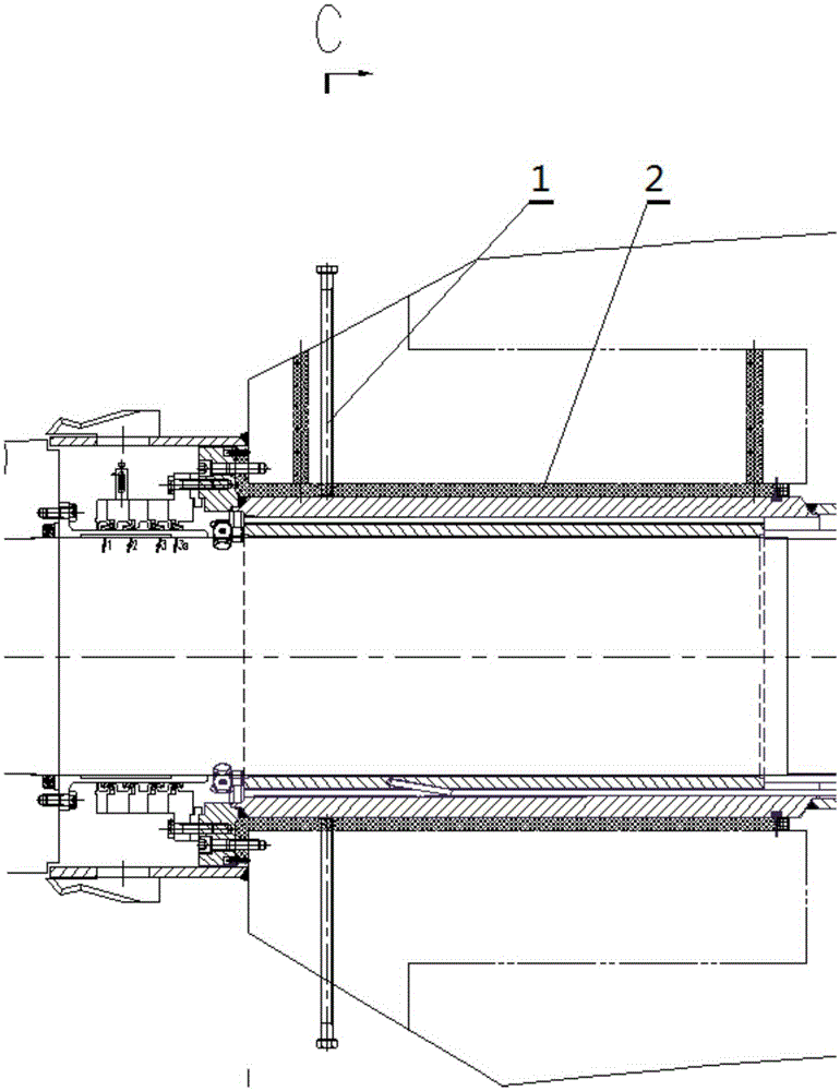
[0037] Such as Image 6 As shown, the epoxy spacers are installed at the front and rear bearing positions of the shafting. Therefore, the positioning of the shafting needs to be calibrated before epoxy pouring and installation, that is, the position of the B-B and E-E section in the figure;

[0038] The installation position of the selected adjustment component should avoid the position of installation bolts such as shaft seals and tail pipe fasteners, such as Image 6 As shown in the section B-B and E-E;

[0039] Such as Figure 9-10 As shown, the adjustment component is installed on the protruding part of the integral stern tube. The adjustment bracket is welded to the hull stern column and the front bearing cast steel. The adjustment bolts apply pressure to the stern tube from the front, rear, left, and right directions of the shaft system to achieve the adjust...


PUM


Abstract

The invention relates to a ship shafting integral tail pipe alignment positioning structure and positioning method. An adjusting bracket and adjusting bolts are arranged at each of the front and rear ends of a ship shafting tail pipe; each adjusting bracket is L-shaped, and one end of the adjusting bracket is transversely welded and fixed onto one corresponding fixing base; two pairs of the adjusting bolts are respectively arranged at the front and rear ends, perpendicularly penetrate through two side surfaces of the respective adjusting brackets, and are respectively propped against the ship shafting tail pipe axially and radially, so as to adjust the axial and radial positions of the ship shafting tail pipe; after positioning is finished, an epoxy cushion block is cast between the ship shafting tail pipe and the fixing bases; the adjusting brackets are disassembled, the exposed parts of the adjusting bolts are cut off, and sealing treatment is performed; the fixing base at the front part of the ship shafting tail pipe is a bearing steel casting, and the fixing base at the rear part of the ship shafting tail pipe is a sternpost. Through adoption of the structure and method provided by the invention, alignment positioning is performed on the ship shafting tail pipe in a three-dimensional space, so as to greatly improve the mounting accuracy; the adjusting bolts are not in contact with an epoxy medium, and bubbles and the like are unlikely to generate on the contact surfaces, so that the quality of epoxy casting can be effectively improved.

Description

Technical field [0001] The invention relates to a ship shafting integral stern tube alignment positioning structure and a positioning method, and belongs to the technical field of ship stern shaft positioning. Background technique [0002] The positioning design of existing ships before stern tube epoxy installation mostly adopts traditional design methods: Figure 1-Figure 5 As shown, the front and rear bearing casts of the ship’s stern tube are drilled, and positioning bolts 1 and 3 are installed to adjust the up, down, left and right positions of the shafting stern tube 30. Under the premise of meeting the accuracy requirements of the alignment, the positioning bolts After fixing and completing the positioning of the shaft system, then pouring the epoxy block 2 and maintaining the state until the block is solidified, and the entire installation process is completed. [0003] The existing technology has the following disadvantages: [0004] 1. The shaft system cannot be accurately ...

Claims


Application Information

Patent Timeline
Patent Type & Authority Applications(China)
IPC IPC(8): B63B9/00B63H23/36
Inventor 徐麟
Owner SHANGHAI MERCHANT SHIP DESIGN & RES INST
Learn More