
Self-balancing loading device for batch concrete-filled steel tubes

A technology of steel tube concrete and loading device, which is applied in the direction of applying stable tension/pressure to test the strength of materials, which can solve the problems of damage, expensive presses, frequent use, etc., and achieve the effect of improving test efficiency

Active Publication Date: 2016-01-20
WUHAN UNIV
View PDF7 Cites 11 Cited by
  • Summary
  • Abstract
  • Description
  • Claims
  • Application Information

AI Technical Summary

Problems solved by technology

At present, the loading devices generally used in the test are large-scale reaction frames, presses, and heavy loads. There are four outstanding problems in this. First, this kind of loading needs to be loaded for a long time, which will take a long time Large-scale reaction frames or presses, but reaction frames and presses are expensive, limited in number and frequently used, and are not easy or even impossible to occupy for a long time; second, large-scale reaction frames and presses will experience force relaxation when they are loaded for a long time. It will affect the accuracy of the test; third, these loading devices cannot complete the loading of one device for multi-component and multi-loading systems; fourth, many of these loadings require destructive tests, and the destructive tests will be unloaded first and then transported Then the loading failure is different from the failure of the actual component under continuous loading

Method used


Image

  • Self-balancing loading device for batch concrete-filled steel tubes
  • Self-balancing loading device for batch concrete-filled steel tubes
  • Self-balancing loading device for batch concrete-filled steel tubes

Examples


Embodiment Construction

[0023] In order to further explain the technical scheme of the present invention, the invention is described in detail below through specific examples:

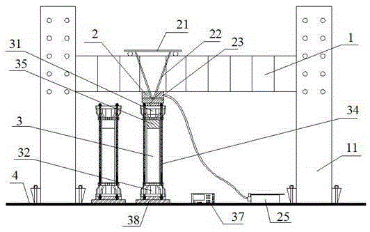
[0024] see Figure 1 to Figure 9 As shown, a self-balancing loading device for batch concrete filled steel tubes includes a reaction frame, a jack 2, an upper cover plate 31, a lower cover plate 32 and steel pipes 3 for pouring concrete;

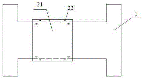
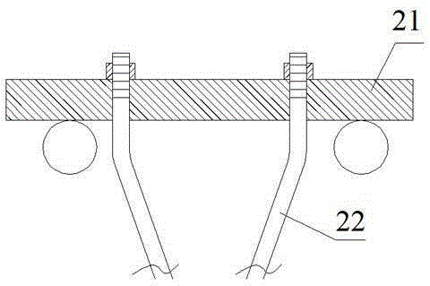
[0025] Described reaction force frame is made up of I-shaped reaction force frame crossbeam 1 and four reaction force frame pillars 11, and described four reaction force frame pillars 11 upper ends are connected with the upper and lower beams of I-shaped reaction force frame crossbeam 1 respectively. The ends are fixedly connected by anchor bolts, and the lower ends of the four reaction frame pillars 11 are fixedly connected with the hardened concrete ground 4 by anchor bolts. The reaction frame beam 1 is provided with a sliding trolley 21 that can slide along the beam. A jack 2 with a low...


PUM


Abstract

The invention relates to a self-balancing loading device for batch concrete-filled steel tubes. The self-balancing device comprises a reaction frame, a jack, an upper cover plate, a lower cover plate and a steel tube for allowing concrete pouring, wherein a sliding trolley is arranged above a reaction frame cross beam, and the jack, the upper cover plate, a pressure sensor, the steel tube, the lower cover plate and a bottom plate located on the concrete ground are sequentially arranged below the reaction frame cross beam; the steel tube is clamped between the upper cover plate and the lower cover plate through four double-headed thread pull rods, the steel tube subjected to concrete pouring is pressurized by the jack, nuts on the four double-headed thread pull rods are tightened, so that the concrete-filled steel tube is still continuously loaded after pressure release of the jack, and then the jack is transferred to another position through the sliding trolley for loading of the next steel tube requiring concrete pouring; the steel tube loading device belongs to an inner self-balancing system and does not need external force for maintenance, batch loading of the concrete-filled steel tubes can be realized through sliding of the trolley on the reaction frame cross steel beam, and the device is simple in structure and convenient to manufacture.

Description

Technical field [0001] The invention relates to the field of performance testing of steel pipe concrete, in particular to a steel pipe concrete self-balancing loading device. Background technique [0002] With the wide application of CFST in high-rise, super high-rise buildings and long-span bridges, the research on CFST is a hot spot in many universities and research institutions. Creep and other research is a very important aspect, which involves the equipment requirements for long-term loading, multi-stage loading, and sustained loading of CFST column specimens. At present, the loading devices generally used in the test are large-scale reaction frames, presses, and heavy loads. There are four outstanding problems in this. First, this kind of loading needs to be loaded for a long time, which will take a long time Large-scale reaction frames or presses, but reaction frames and presses are expensive, limited in number and frequently used, and are not easy or even impossible...

Claims


Application Information

Patent Timeline
Patent Type & Authority Applications(China)
IPC IPC(8): G01N3/12
Inventor 余敏鲍浩李书磊叶建乔
Owner WUHAN UNIV
Learn More