Linear motor position detection system

A linear motor and detection system technology, applied in electric/magnetic position measurement, electromechanical devices, propulsion systems, etc., can solve the problem of increasing the number of 43 magnetic sensors, and achieve the effect of easy installation and adjustment

Active Publication Date: 2010-03-24
THK CO LTD
View PDF0 Cites 15 Cited by
  • Summary
  • Abstract
  • Description
  • Claims
  • Application Information

AI Technical Summary

Problems solved by technology

But, this method has brought the number of magnetic sensor 43 to increase

Method used


Image

  • Linear motor position detection system
  • Linear motor position detection system
  • Linear motor position detection system

Examples


Embodiment Construction

[0094] 【0022】

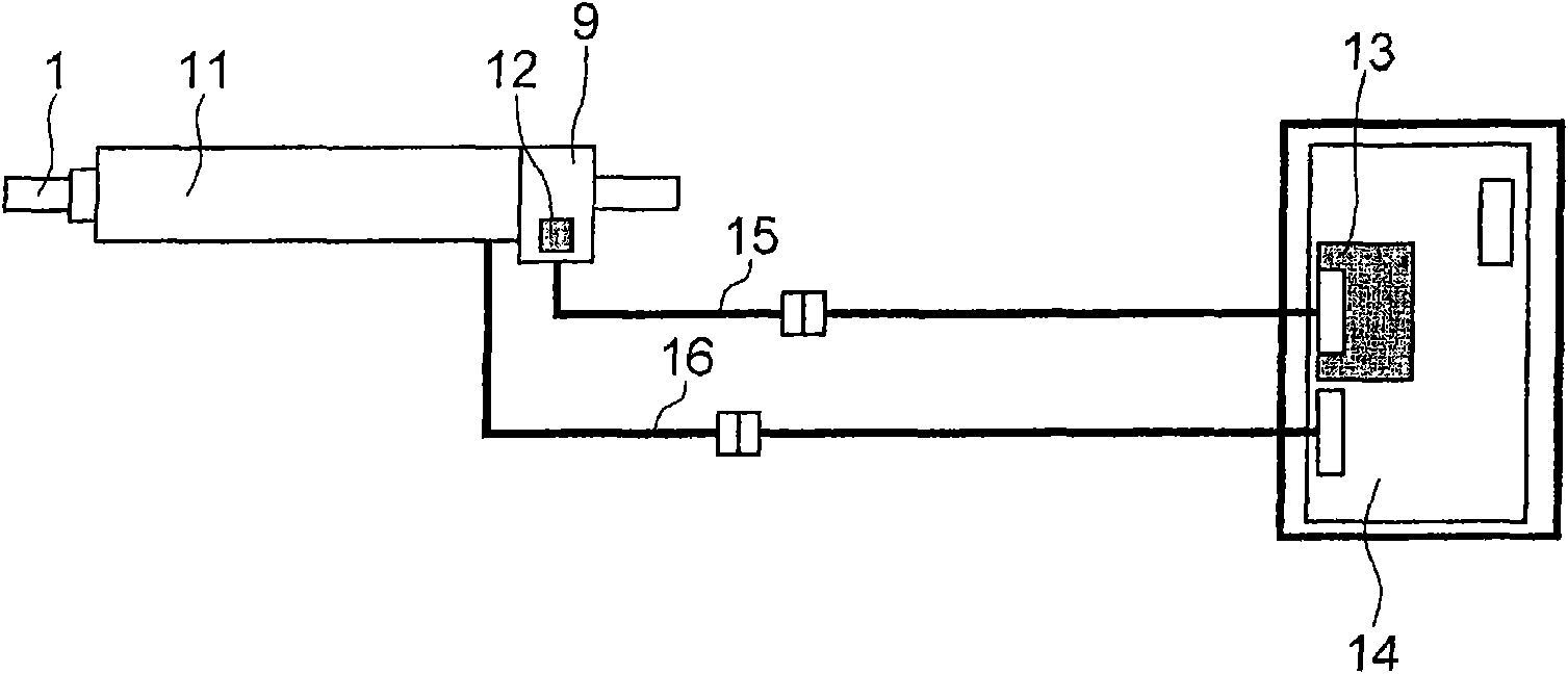
[0095] Hereinafter, embodiments of the present invention will be described in detail with reference to the drawings. figure 1 The position detection system of the linear motor in one embodiment of this invention is shown. The position detection system includes: a linear motor 11 ; a magnetic sensor 12 , which detects the position of the core rod 1 of the linear motor 11 ; and a position detection circuit 13 , which interpolates the signal output by the magnetic sensor 12 . The signal of the position output by the position detection circuit 13 is output to the driver 14 of the linear motor 11 . In the driver 14, a power converter such as a PWM converter (PWM: Pulse Width Modulation), and a controller are incorporated, wherein the power converter provides power set to be suitable for controlling the linear motor 11, and the controller wherein Signals from the position detection circuit 13 and commands from the host computer control the power converter. The ma...


PUM


Abstract

Provided is a position detection system which can be realized at a low cost without requiring a strict management of sensor mounting accuracy. The position detection system includes: a linear motor (11) having a rod (1) in which N-poles and S-poles are alternately arranged in the axial direction and a plurality of coils (4) surrounding the rod (1); a magnetic sensor (12) which detects a change ofthe magnetic field direction of the rod (1) generated by a relative rectilinear motion of the rod (1) with respect to the coils (4) and outputs a sine wave signal and a cosine wave signal having a phase difference of 90 degrees; and a position detection circuit (13) which detects a relative position of the rod (1) with respect to the coils (4) according to the sine wave signal and the cosine wavesignal. Since the magnetic sensor (12) detects the change of the magnetic field direction of the rod (1), no change is caused in the sine wave signal and the cosine wave signal outputted by the magnetic sensor (12) even if the distance between the rod (1) and the magnetic sensor (12) is shifted.

Description

technical field [0001] 【0001】 [0002] The present invention relates to a linear motor position detection system for detecting the position of a linear motor that obtains thrust by passing a current through a magnetic field of a magnet and a coil. Background technique [0003] 【0002】 [0004] One type of linear motor, that is, a rob type linear motor has a structure in which a plurality of cylindrical coils are stacked, and a core rod is inserted into a hole of the stacked coil. N poles and S poles are alternately arranged on the core rod. When the three-phase coil divided into U / V / W phases flows through three-phase currents with different phases every 120°, and when the moving magnetic field in which the axis of the coil moves is generated, the core rod obtains thrust through the moving magnetic field, and moves The speed of the magnetic field is synchronized for linear motion. [0005] 【0003】 [0006] In order to control the movement of the core rod, it is necessary t...

Claims


Application Information

Patent Timeline
Patent Type & Authority Applications(China)
IPC IPC(8): G01D5/245G01B7/00H02K41/02H02K41/03G05D3/12
CPCG01B7/003H02K11/0021G01D5/2451H02K41/03H02K11/215
Inventor 浅生利之山中修平东条敏郎
Owner THK CO LTD
Why Eureka
Try Eureka