Tunnel-vault distributed optical fiber monitoring device, construction technology thereof and monitoring method thereof

A distributed optical fiber and monitoring device technology, applied in the field of sensors, can solve the problems of increased workload and equipment cost, multi-point easy missed detection, real-time, parallel and low degree of automatic monitoring, etc., to reduce potential safety hazards and operational risks , long-distance real-time online measurement, and the effect of improving the overall economic benefits

Active Publication Date: 2016-01-20
DALIAN UNIV
View PDF9 Cites 9 Cited by
  • Summary
  • Abstract
  • Description
  • Claims
  • Application Information

AI Technical Summary

Problems solved by technology

[0003] (1) Multi-point type is easy to miss detection: point-type detection method layout points, the most dangerous place may be missed detection, there are blind spots; increasing the number of monitoring points, although the reliability of the results is improved, but the workload and equipment costs are greatly increased , considering factors such as economy and efficiency, it is difficult to infinitely deploy various detection probes or sensors in actual engineering or research projects;
[0004] (2) High dependence on engineering environment: Traditional technology has slow monitoring speed and low efficiency, and requires specialized operators, while tunnel engineering conditions are often complex, and traditional electrical sensors are sensitive to humidity, temperature, electromagnetic fields and other environmental factors
[0005] (3) The degree of real-time, parallel and automatic monitoring is not high, and there is a lack of long-distance technology and large-area monitoring methods

Method used


Image

  • Tunnel-vault distributed optical fiber monitoring device, construction technology thereof and monitoring method thereof
  • Tunnel-vault distributed optical fiber monitoring device, construction technology thereof and monitoring method thereof
  • Tunnel-vault distributed optical fiber monitoring device, construction technology thereof and monitoring method thereof

Examples


Embodiment Construction

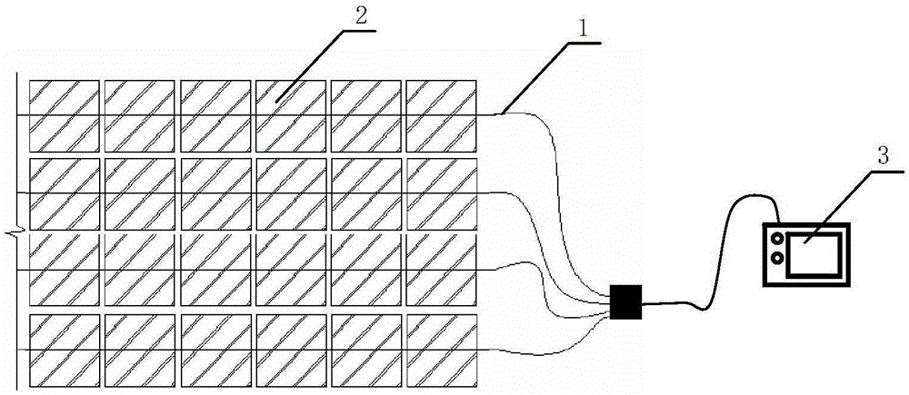
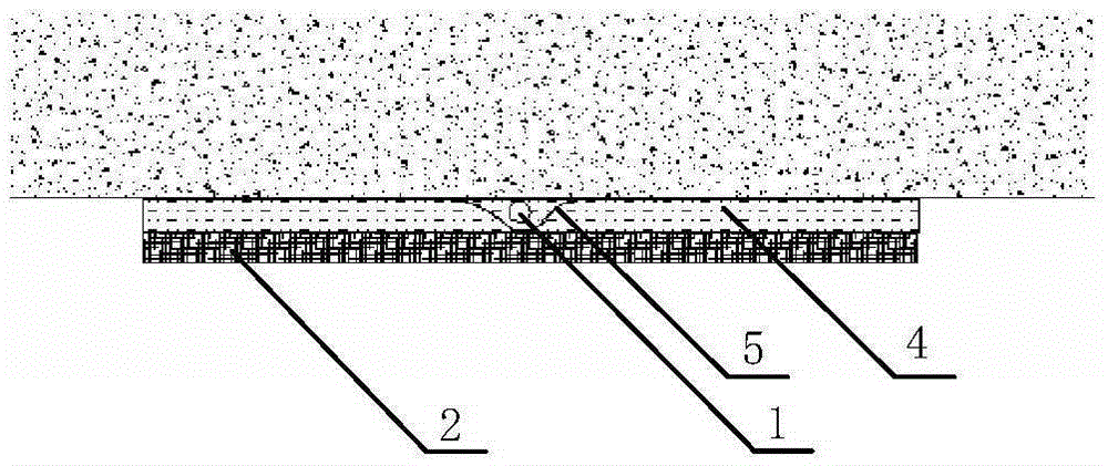
[0035] The specific embodiment of the present invention is shown in the accompanying drawings, the tunnel vault distributed optical fiber monitoring device is characterized in that the distributed optical fiber monitoring device includes: optical fiber 1, fiber cloth block 2, optical time domain reflectometer 3 and polyamide Imide tape 5; the optical fiber 1 is pasted on the tunnel vault through the polyimide tape 5; then the fiber cloth 2 is pasted on the outside of the pasted optical fiber 1 and the polyimide tape 5 with epoxy resin glue 4; One end of each optical fiber 1 is connected with an optical time domain reflectometer 3 .

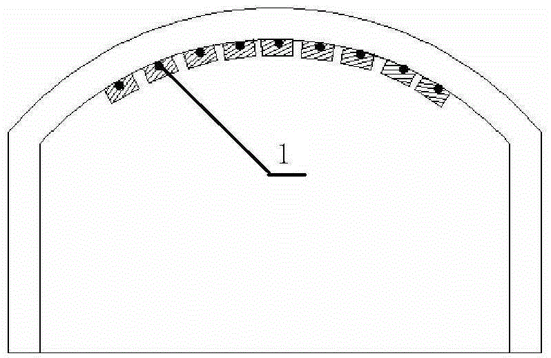
[0036] The optical fibers 1 are parallel and evenly distributed on the vault of the tunnel along the tunnel direction.

[0037] Multiple optical fibers 1 are arranged according to the width of the tunnel section. The optical fiber 1 is located on the central axis of the fiber cloth 2 covering it.

[0038] The fiber cloth 2 is a flame-retardant g...


PUM

PropertyMeasurementUnit
sizeaaaaaaaaaa

Abstract

The invention discloses a tunnel-vault distributed optical fiber monitoring device, a construction technology thereof and a monitoring method thereof, belongs to the technical field of sensors, and particularly relates to design of a tunnel-vault distributed optical fiber monitoring device, a construction technology thereof and a monitoring method thereof. The distributed optical fiber monitoring device comprises optical fibers, fiber cloth blocks, an optical time domain reflectometer and polyimide adhesive tape. The optical fibers are pasted to a tunnel vault through the polyimide adhesive tape, and then the fiber cloth blocks are pasted outside the pasted optical fibers and the pasted polyimide adhesive tape through epoxy resin glue; one ends of the optical fibers are connected with the optical time domain reflectometer. The distributed optical fiber monitoring device has the advantages of being novel in structure, convenient to install, low in manufacturing cost, capable of achieving the all-dimensional effect, free of blind areas, capable of achieving total time domain monitoring and the like; the distributed optical fiber monitoring device belongs to a novel tunnel-vault distributed optical fiber monitoring device integrating economical efficiency and practicability.

Description

technical field [0001] The tunnel vault distributed optical fiber monitoring device and its construction technology and monitoring method described in the present invention belong to the field of sensor technology, and in particular relate to the design of a tunnel vault real-time monitoring method based on distributed optical fibers. Background technique [0002] The existing tunnel detection technology mainly adopts Brillouin scattering technology (BOTDR), and its monitoring method focuses on structural displacement, strain and settlement, etc., and has the following limitations: [0003] (1) Multi-point type is easy to miss detection: point-type detection method layout points, the most dangerous place may be missed detection, there are blind spots; increasing the number of monitoring points, although the reliability of the results is improved, but the workload and equipment costs are greatly increased , considering factors such as economy and efficiency, it is difficult t...

Claims


Application Information

Patent Timeline
Patent Type & Authority Applications(China)
IPC IPC(8): G01N21/88
Inventor 王桂萱夏梦颖赵杰
Owner DALIAN UNIV
Why Eureka
Try Eureka