
A deformable mirror device capable of producing various aberrations

A technology of deformable mirrors and aberrations, applied in optical components, optics, instruments, etc., can solve problems such as difficult control of effective aberration accuracy and rigid body displacement error, and achieve the effect of improving accuracy and reducing rigid body displacement error

Inactive Publication Date: 2017-12-26
CHANGCHUN INST OF OPTICS FINE MECHANICS & PHYSICS CHINESE ACAD OF SCI
View PDF15 Cites 1 Cited by
  • Summary
  • Abstract
  • Description
  • Claims
  • Application Information

AI Technical Summary

Problems solved by technology

[0005] In order to solve the problems existing in the existing patents that the simultaneous loading of axial force, tangential moment, and radial moment cannot be realized only by loading force on the extension, and it is difficult to control the accuracy of effective aberration and the displacement error of rigid body, A new type of deformable mirror device capable of generating multiple aberrations is proposed

Method used


Image

  • A deformable mirror device capable of producing various aberrations
  • A deformable mirror device capable of producing various aberrations
  • A deformable mirror device capable of producing various aberrations

Examples


Embodiment Construction

[0024] The present invention will be described in further detail below in conjunction with the accompanying drawings.

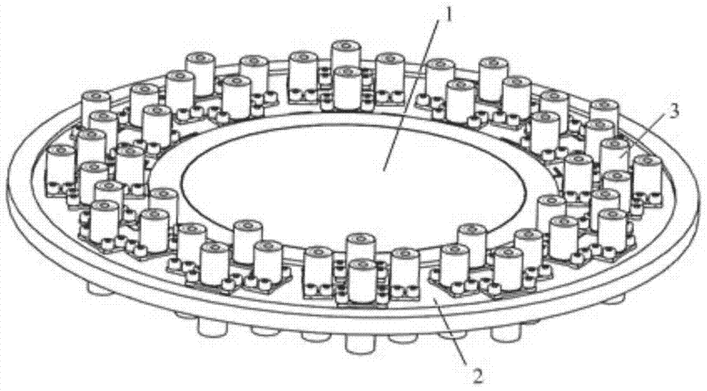
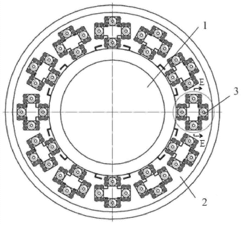
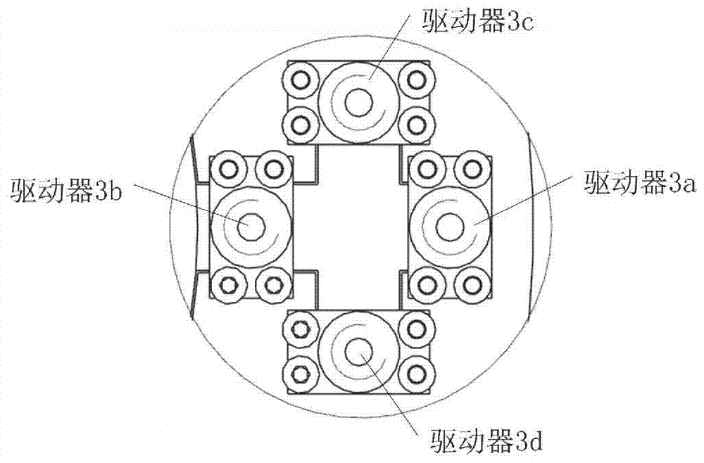
[0025] A deformable mirror device capable of producing various aberrations, such as Figure 1-6 As shown, the deformable mirror device includes an optical element 1 , a deformable mirror frame 2 and a driver 3 . The optical element 1 and the deformable spectacle frame 2 are connected to form a spectacle frame assembly by gluing or pressing. A plurality of drivers 3 are respectively fixed on the outer ring of the deformable mirror frame, and the input force acts on the driving arms 2-4 of the deformable mirror frame 2 .

[0026] Such as Figure 7 As shown, the deformable mirror frame 2 is an integrated structure that connects the outer ring 2-2 of the mirror frame and the inner ring 2-1 of the mirror frame by a plurality of flexible blocks 2-3 evenly distributed in the circumferential direction. Drive arms 2-4 are distributed among them.

[0027] The drivi...


PUM


Abstract

A deformable mirror device capable of generating various aberrations belongs to the field of system aberration compensation of optical systems. In order to solve the problem in existing patents that the axial force, tangential moment, and Simultaneous loading of radial torque makes it difficult to control the accuracy of effective aberrations and rigid body displacement errors. The optical components of the device and the deformable mirror frame are connected into a mirror frame assembly by gluing or pressing, and multiple drivers are respectively fixed on the on the outer ring of the deformable mirror frame, and the input force acts on the driving arm of the deformable mirror frame; the deformable mirror frame is an integrated structure that connects the outer ring of the mirror frame and the inner ring of the mirror frame by a plurality of flexible blocks uniformly distributed in the circumferential direction, There is a driving arm distributed between every two adjacent flexible blocks; the driving arm is connected to the inner ring of the mirror frame, and is separated from the outer ring of the mirror frame by a wire-cut slit; the cross-section of the driving arm is in the form of a cross beam structure, and eight drivers Act respectively on the upper and lower sides of the four ends of the cross beam.

Description

technical field [0001] The invention relates to a deformable mirror device capable of producing multiple aberrations in optical elements, belonging to the field of system aberration compensation of optical systems, in particular to system aberration compensation in lithography projection objective lens systems. Background technique [0002] When the projection objective lens system works under normal lighting, ring lighting, dipole lighting, quadrupole lighting and other working conditions, the thermal load will cause the wave aberration of the system to deteriorate, resulting in Z5, Z6, Z7, Z8, Z12, Components such as Z13, Z17, Z18, Z28, Z29 become larger, so they need to be compensated. [0003] U.S. Patent US6388823B1 discloses a Z5 astigmatic deformable mirror device, which includes optical elements, a deformable support ring, a frame, and a pneumatic bellows driver. Tongues are distributed outside the deformable support ring, and the deformable support ring and the fram...

Claims


Application Information

Patent Timeline
Patent Type & Authority Patents(China)
IPC IPC(8): G02B26/06
CPCG02B26/06
Inventor 赵磊东立剑张敏张德福李显凌张巍隋永新杨怀江
Owner CHANGCHUN INST OF OPTICS FINE MECHANICS & PHYSICS CHINESE ACAD OF SCI
Learn More