Air and space-based radio frequency signal optical fiber remote transmission timing system

A technology of radio frequency signal and radio frequency light, which is applied in the direction of optical fiber transmission, etc., can solve the problems that can not perfectly solve the problems of air space-based radio frequency signal reference source signal access, time synchronization defects, synchronization equipment degradation, etc.

Active Publication Date: 2019-03-26
电信科学技术第五研究所有限公司
View PDF8 Cites 0 Cited by
  • Summary
  • Abstract
  • Description
  • Claims
  • Application Information

AI Technical Summary

Problems solved by technology

This solution can solve the application of frequency and time synchronization, but there are two problems: one is to reduce the synchronization equipment originally used as a first-level node to a second-level node synchronization equipment in terms of networking; the other is to upgrade the existing synchronization equipment The GPS / BD input unit is modified (the current PRC / LPR equipment adopts the radio frequency interface mode) to adapt to the access of the baseband signal
This solution does not need to modify the synchronization equipment, but there is also the problem of downgrading the local synchronization equipment, and there are also defects in time synchronization
[0007] To sum up, the current various solutions have their own problems, and they cannot perfectly solve the access of reference source signals of space-based radio frequency signals in the air.

Method used


Image

  • Air and space-based radio frequency signal optical fiber remote transmission timing system
  • Air and space-based radio frequency signal optical fiber remote transmission timing system
  • Air and space-based radio frequency signal optical fiber remote transmission timing system

Examples


Embodiment 1

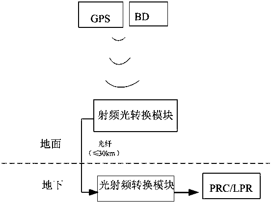
[0063] Such as figure 1 and figure 2 and image 3 shown. figure 1 BD in refers to the Chinese Beidou satellite.

[0064] The space-based radio frequency signal optical fiber remote time transmission system includes the following structure:

[0065] Antenna: used to receive space-based radio frequency signals in the air,

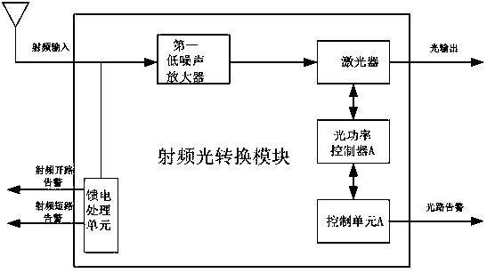
[0066] RF-to-optical conversion module: used to receive the air space-based radio frequency signal output by the antenna, and perform low-noise amplification processing on the air space-based radio frequency signal, and then convert it into an optical signal output by the laser;

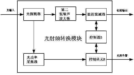
[0067] Optical radio frequency conversion module: used to receive the optical signal output by the radio frequency optical conversion module, and convert the change of the optical power of the optical signal into a corresponding current signal, and perform low-noise amplifier processing on the current signal, and then restore it to Space-based RF signals in the air;

[0068] ...


PUM


Abstract

The invention discloses an optical fiber remote transmission timing system of air space-based radio frequency signals. The optical fiber remote transmission timing system comprises the following structures: an antenna used for receiving an air space-based radio frequency signal; a radio frequency-optical conversion module used for receiving the air space-based radio frequency signal output by the antenna, carrying out low noise amplification processing on the air space-based radio frequency signal, converting the air space-based radio frequency signal into an optical signal by a laser and outputting the optical signal; an optical-radio frequency conversion module used for receiving the optical signal output by the radio frequency-optical conversion module, converting the change of the optical power of the optical signal into a corresponding current signal, carrying out low noise amplification processing on the current signal and reducing the current signal into the air space-based radio frequency signal through numerical control attenuation processing; an optical fiber used for transmitting the optical signal output by the radio frequency-optical conversion module to the optical-radio frequency conversion module; and a PRC or LPR device used for receiving the air space-based radio frequency signal output by the optical-radio frequency conversion module.

Description

technical field [0001] The invention relates to the long-distance transmission technology of air space-based radio frequency signals, in particular to an air space-based radio frequency signal optical fiber remote transmission timing system. Background technique [0002] As the synchronization device of the supporting network, in the networking application, the primary node device (PRC / LPR) needs a high-precision reference source. At present, it is generally used to obtain the reference signal from the space-based radio frequency signal (GPS / BeiDou) in the air for transmission. Network equipment provides high-precision time and frequency synchronization signals. However, the acquisition of space-based radio frequency signals in the air requires certain conditions, that is, the antenna must be fixed in a place open to the sky, and at the same time, the length of the feeder is limited to within 200 meters to ensure that the synchronization equipment can receive satellite signa...

Claims


Application Information

Patent Timeline
Patent Type & Authority Patents(China)
IPC IPC(8): H04B10/25
Inventor 胥骥楚鹰军
Owner 电信科学技术第五研究所有限公司
Why Eureka
Try Eureka