Oil smoke filtering device

A technology for oil fume filtration and oil fume, which is applied in the direction of oil fume removal, household heating, heating methods, etc., can solve problems such as large resistance loss, increase maintenance cycle, improve oil fume separation efficiency, and improve the effect of oil fume separation

Active Publication Date: 2016-01-27
NINGBO FOTILE KITCHEN WARE CO LTD
View PDF8 Cites 16 Cited by
  • Summary
  • Abstract
  • Description
  • Claims
  • Application Information

AI Technical Summary

Problems solved by technology

Although the oil fume separation plate has a certain oil fume separation effect after forming a bent air duct that changes the wind direction sharply, it has the following two main defects: first, the resistance loss is large; second, only large-sized particles can hit Oil filter plate, small particles will flow away with the airflow

Method used


Image

  • Oil smoke filtering device
  • Oil smoke filtering device
  • Oil smoke filtering device

Examples


Embodiment 1

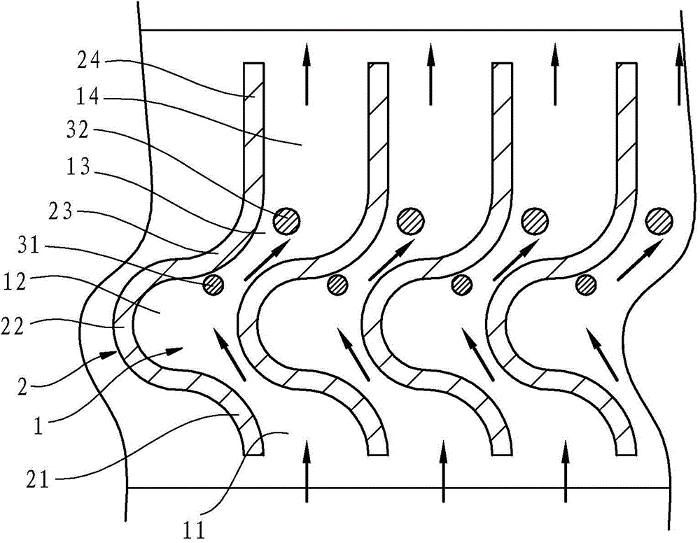
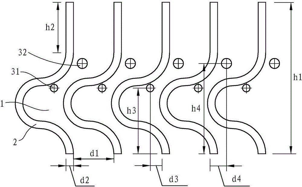
[0038] Such as figure 1 with figure 2 As shown, the oil fume filter device in this embodiment includes a plurality of filter channels arranged vertically and arranged side by side in the horizontal direction, and only four of the filter channels 1 are shown in the figure, and the arrows in the filter channels 1 indicate the flow direction of oil fume. In this embodiment, each filter channel 1 is an arc-shaped zigzag channel and is formed by adjacent vertical partitions 2 respectively. The filter channel 1 is the air intake area 11 from bottom to top, where the oil fume concentrates and collides. The filter area 12 and the air outlet area 13, where the oily fume concentrates and collides with the filter area 12, is the zigzag part of the zigzag channel. In this embodiment, each partition plate 2 has the same shape and is an integral structure. The cross section of the partition plate 2 includes a first arc segment 21, a second arc segment 22 and a third arc segment connected ...

Embodiment 2

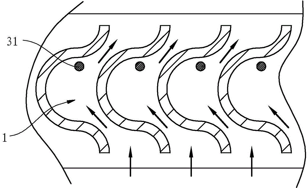
[0059] Such as image 3 As shown, compared with the structure in Embodiment 1, the oil fume filtering device in this embodiment omits the linear rectification channel and the second oil fume blocking member, and the first oil fume blocking member 31 in the filtering channel 1 continues to remain. The rest of the structure is the same as that in Embodiment 1, and will not be described here.

Embodiment 3

[0061] Such as Figure 4 As shown, the filter channel in this embodiment is a bent filter channel 10, the air inlet rectifying channel 101 is located below the bent filter channel 10, and the air outlet rectifying channel 102 is located above the bent filter channel 10. Inside the filter channel 10 are provided two rod-shaped oil fume stoppers, namely a lower stopper 33 at the bottom and an upper stopper 34 at the top. The cross sections of the lower stopper 33 and the upper stopper 34 are circular. Each bent partition 20 is formed by bending the straight section 201 up and down sequentially, and the combination of the curved parts of two adjacent bent partitions 20 makes the filtering channel appear as a zigzag channel. The bending angle between adjacent straight segments 201 constituting the cross-section of the bending portion is 60-90 degrees. In this embodiment, the cross-section of the bending part includes three straight segments 201, the total height of the bending pa...


PUM

PropertyMeasurementUnit
widthaaaaaaaaaa
diameteraaaaaaaaaa
diameteraaaaaaaaaa

Abstract

The invention discloses an oil smoke filtering device. The oil smoke filtering device comprise at least two vertically arranged filtering channels; the filtering channels are arranged in parallel along the transverse direction; each filtering channel is composed of adjacent vertically arranged separating plates, and possesses at least on zigzag part, so that at least one filtering channel is a zigzag channel; and oil smoke blocking parts are transversely arranged in the filtering channels. Advantages are that: filtering channel area and contact area with oil smoke of the zigzag channels are relatively large, and fluidity of grease obtained via filtering is high; resistance loss of the transverse oil smoke blocking parts arranged in the filtering channels is small, collision filtering effect on particles with different size is excellent, oil smoke separation and filtering effect can be improved effectively without obvious increasing of windage resistance, and excellent oil smoke separation efficiency is obtained via combination with the zigzag channels; the oil smoke filtering device is simple in the whole structure, is convenient for maintenance, and is suitable for oil smoke filtering of a plurality of smoke exhaust ventilators.

Description

technical field [0001] The invention relates to a range hood, in particular to an oil fume filtering device for separating the oil fume in the gas. Background technique [0002] At present, most of the oil fume purification devices of the collision method on the market adopt mesh or labyrinth type, reverse buckle type purification structure, etc. The mesh structure filter structure is related to the diameter of the hole. The smaller the hole, the better the oil fume filtration effect, but the wind resistance is large and the durability is poor. , it is easy to block and cause failure, and the maintainability is poor; the labyrinth filter structure changes the flow direction through multiple protruding plate structures in the flow channel, and the wind resistance is large, and the filtering effect is related to the number of labyrinths; various shapes of buckle filter structures, The filtration effect is related to the size of the flow channel, the flow channel is small, the ...

Claims


Application Information

Patent Timeline
Patent Type & Authority Applications(China)
IPC IPC(8): B01D45/06B01D45/08F24C15/20
Inventor 曹亚裙茅忠群诸永定
Owner NINGBO FOTILE KITCHEN WARE CO LTD
Why Eureka
Try Eureka