
Automatic welding device for barrel

An automatic welding and barrel technology, applied in welding monitoring devices, welding power sources, welding equipment, etc., can solve the problems of high labor intensity, low production efficiency, poor product quality, etc., to reduce labor costs, improve production efficiency and product quality. quality effect

Active Publication Date: 2016-01-27
SHENZHEN PREVAIL TECH
View PDF7 Cites 9 Cited by
  • Summary
  • Abstract
  • Description
  • Claims
  • Application Information

AI Technical Summary

Problems solved by technology

[0003] The purpose of the present invention is to provide an automatic welding device for cylinders, which is used to solve the problems of high labor intensity, low production efficiency and poor product quality caused by manual welding of cylinders

Method used


Image

  • Automatic welding device for barrel
  • Automatic welding device for barrel
  • Automatic welding device for barrel

Examples


Embodiment Construction

[0020] The present invention will be further elaborated below with reference to the accompanying drawings.

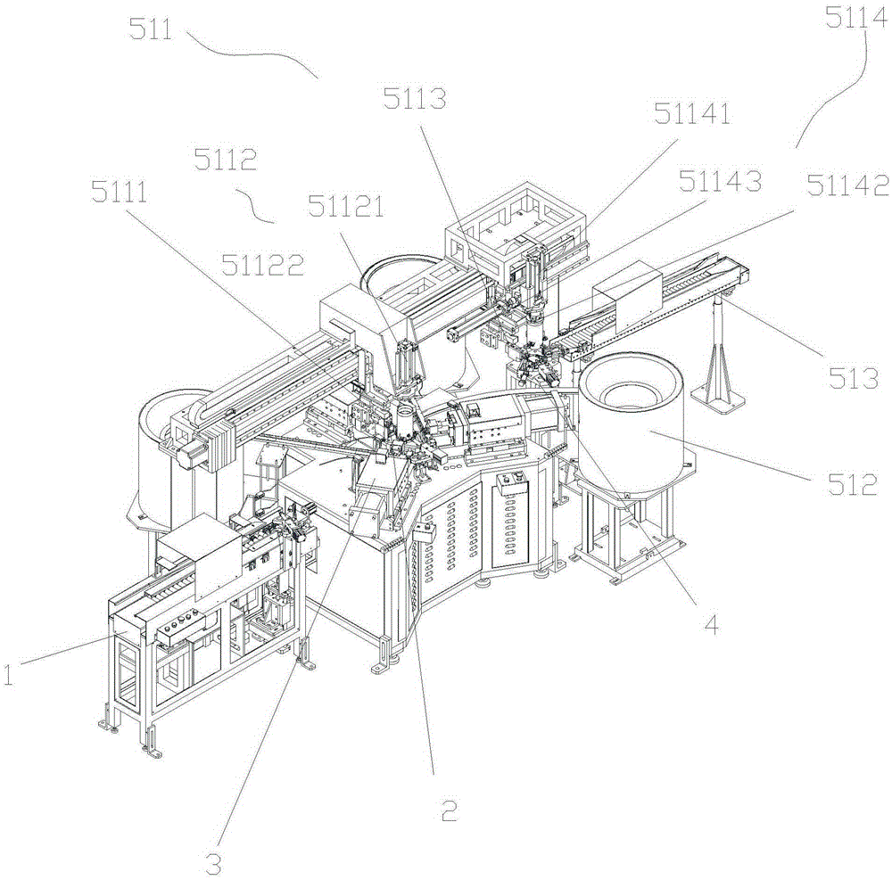
[0021] Please refer to the attached figure 1 to attach Figure 15 , the cylinder automatic welding device, which includes: a machine frame, an industrial computer, a feeding frame assembly 1, a feeding assembly 2, a welding assembly 3 and a detection assembly 4.

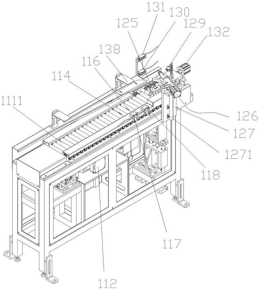
[0022] Please refer to the attached figure 1 to attach Figure 5 , The feeding frame assembly 1 includes the following structure: the conveyor frame 111 is provided with a roller assembly 1111, and the motor 112 is installed under the conveyor frame 111 to drive the roller assembly 1111 to move. One end of the conveyor frame 111 is the feeding end, and the other end is provided with three stations, which are successively from the feeding end: the blocking station, the releasing station, and the feeding preparation station. The stop material station is provided with the first stop material cylinder 113 belo...


PUM


Abstract

The invention discloses an automatic welding device for a barrel. The automatic welding device comprises a rack, an industrial personal computer arranged on the rack, a transfer mechanism arranged on the rack, and a feeding frame assembly. Three welding assemblies and three feeding assemblies are arranged on the portion, below the transfer mechanism, of the rack. Under control of the industrial personal computer, the to-be-welded barrel is firstly fed through the feeding frame assembly and transferred to a welding point defined by the three welding assemblies through the transfer mechanism after being positioned through a positioning mechanism, at the moment, L-shaped stand bars are fed through the three feeding assemblies synchronously, a controller is started, and then the L-shaped stand bars and the barrel are welded. According to the automatic welding device for the barrel, automatic equipment is adopted, automation of the feeding, welding and detection overall process is achieved, labor cost is reduced, and production efficiency and product quality are improved.

Description

technical field [0001] The invention relates to the technical field of automatic welding equipment, in particular to an automatic cylinder welding device. Background technique [0002] In the prior art, the process of welding the cylinder body is mainly carried out manually with a welding machine. That is, one person, one machine, manual feeding, unloading and manual inspection. The disadvantage of using manual welding cylinder is that the labor cost is high, the labor intensity is high, and the welding quality cannot be guaranteed. Contents of the invention [0003] The object of the present invention is to provide an automatic cylinder welding device, which is used to solve the problems of high labor intensity, low production efficiency and poor product quality caused by manual welding of cylinders in the prior art. [0004] In order to achieve the above object, the technical scheme proposed in the present invention is: [0005] An automatic cylinder welding device acc...

Claims


Application Information

Patent Timeline
IPC IPC(8): B23K11/00B23K11/31B23K11/36B23K11/25B23K101/04
CPCB23K11/002B23K11/25B23K11/31B23K11/36B23K2101/04
Inventor 刘兴伟
Owner SHENZHEN PREVAIL TECH
Learn More