Pneumatic holding device

A pneumatic clamp and air cylinder technology, applied in the field of tooling and fixtures, can solve the problems of complex liner positioning tooling structure, difficult to guarantee welding quality, and inability to achieve consistent production, etc., to achieve accuracy and stability, simple structure, and volume. small effect

Active Publication Date: 2016-01-27
JIANGSU YOUFU AUTO PARTS TECH CO LTD
View PDF5 Cites 1 Cited by
  • Summary
  • Abstract
  • Description
  • Claims
  • Application Information

AI Technical Summary

Problems solved by technology

The existing liner positioning tool has complex structure, large space occupation, high cost, difficult alignment, and poor posi...

Method used


Image

  • Pneumatic holding device
  • Pneumatic holding device
  • Pneumatic holding device

Examples


Embodiment Construction

[0018] Below in conjunction with accompanying drawing and embodiment the present invention will be further described:

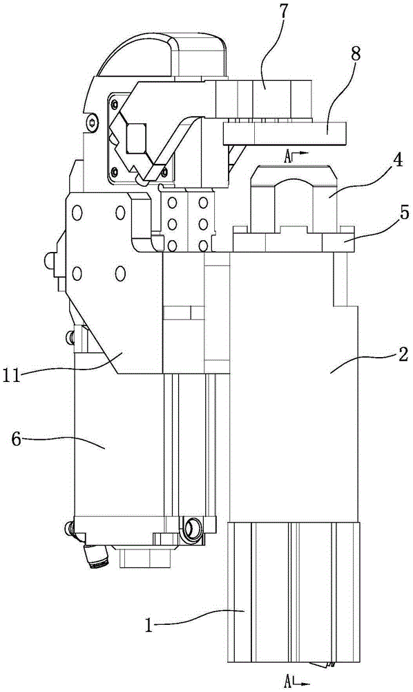
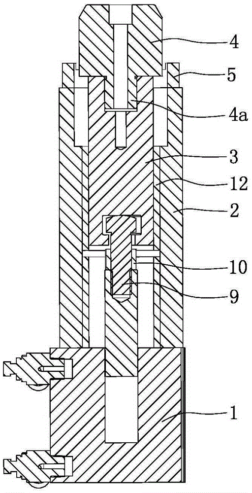
[0019] Such as figure 1 , figure 2 As shown, a guide cylinder 2 is arranged on the cylinder body of the first cylinder 1 , the guide cylinder 2 is located above the cylinder body of the first cylinder 1 , and the guide cylinder 2 is fixedly connected with the cylinder body of the first cylinder 1 . The guide cylinder 2 is a steel structure, and the shape of the guide cylinder 2 is square, that is, the outer contour of the cross section of the guide cylinder 2 is square. The piston rod of the first cylinder 1 extends vertically upwards into the guide cylinder 2, and a guide post 3 is arranged above the piston rod of the first cylinder 1. The guide post 3 is located in the guide cylinder 2, and the guide post 3 and the guide cylinder 2 are embedded. The wear-resistant liner 12 is a sliding fit.

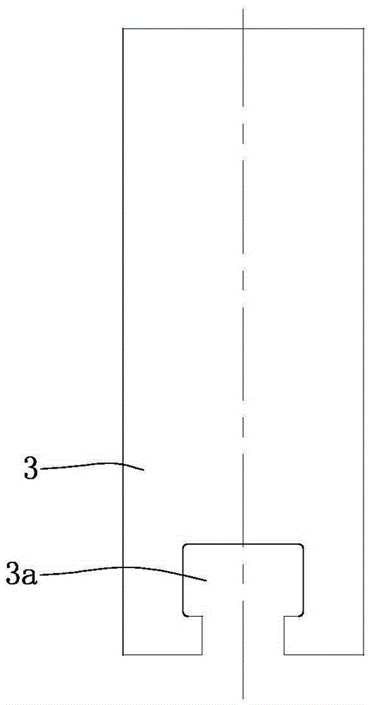
[0020] Such as figure 2 , image 3 As shown, a "T" shaped ...


PUM


Abstract

The invention discloses a pneumatic holding device. A piston rod of a first air cylinder is connected with the lower end of a guide column. A positioning pin is installed at the top end of the guide column. A second air cylinder is installed on a guide barrel and connected with one end of a pressing arm, and a pressing head is fixed to the bottom face of the other end of the pressing arm. Mounting holes are formed in the four corners of a positioning ring, and a convex block is arranged between every two adjacent mounting holes in the circumferential direction. A connector is arranged between the guide column and the piston rod of the first air cylinder. A boss at the head of the connector is clamped into a T-shaped through slot in the lower end of the guide column. The lower end of the connector is in threaded connection with the piston rod of the first air cylinder. The pneumatic holding device is reasonable in design, easy to implement, simple and compact in structure, easy to assemble, small in size and occupied space, low in cost, convenient to control, and flexible and reliable in running. Moreover, liner pipes can be positioned accurately and stably, welding of the liner pipes is facilitated, and the welding quality is guaranteed.

Description

technical field [0001] The invention belongs to the technical field of fixtures, and in particular relates to a pneumatic clamping device. Background technique [0002] The rear axle assembly of the automobile is composed of a beam, a longitudinal arm, a spring seat, a liner, a parking brake cable bracket, an oil pipe bracket and a shock absorber mounting seat, etc., and the longitudinal arms are welded symmetrically at both ends of the beam. Weld liner, parking brake cable bracket, shock absorber mount and oil pipe bracket in sequence. During welding, it is necessary to position the beam, longitudinal arm, spring seat, liner, etc. in different steps with the help of multiple tooling. The existing liner positioning tool has complex structure, large space occupation, high cost, difficult alignment, and poor positioning stability, which makes it difficult to guarantee the welding quality and fail to meet the requirements of consistent production. Contents of the invention ...

Claims


Application Information

Patent Timeline
IPC IPC(8): B23K37/04B23K37/053
CPCB23K37/04B23K37/053B23K2101/006B23K2101/06
Inventor 何强彭政张旭
Owner JIANGSU YOUFU AUTO PARTS TECH CO LTD
Why Eureka
Try Eureka