Split clamp and clamping boards

A split-type fixture technology, applied in workpiece clamping devices, metal processing equipment, clamping, etc., can solve the problems of reduced production efficiency, long replacement time, low safety factor, etc., achieve lightweight replacement, save replacement time, The effect of improving processing efficiency

Pending Publication Date: 2016-01-27
MINO PRECISION DIE CASTING SHANGHAI CO LTD
View PDF0 Cites 1 Cited by
  • Summary
  • Abstract
  • Description
  • Claims
  • Application Information

AI Technical Summary

Problems solved by technology

[0005] However, most of the existing aluminum alloy auto parts fixtures are integral fixtures, and their own weight requires the assistance of multiple people to carry out the replacement, and even mechanical equipment (su

Method used


Image

  • Split clamp and clamping boards
  • Split clamp and clamping boards
  • Split clamp and clamping boards

Examples


Embodiment 1

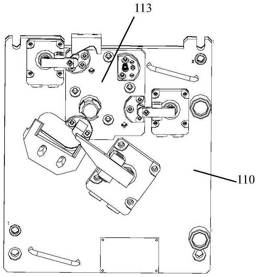
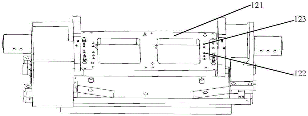
[0039] see Figure 1 to Figure 4 , the present invention discloses a split clamp, which is mainly assembled by a detachable clamping plate 110 and a base plate seat 120 .

[0040] in, figure 1 A schematic diagram of one embodiment of the removable clamping plate of the present invention is shown. The detachable clamping plate 110 is a substantially rectangular plate-like structure (other shapes are also possible, of course), on which at least a workpiece clamping piece 113 is disposed. Optionally, for the convenience of structural arrangement, the driving part of the workpiece clamping member 113 may also be arranged on the detachable clamping plate 110 for easy operation.

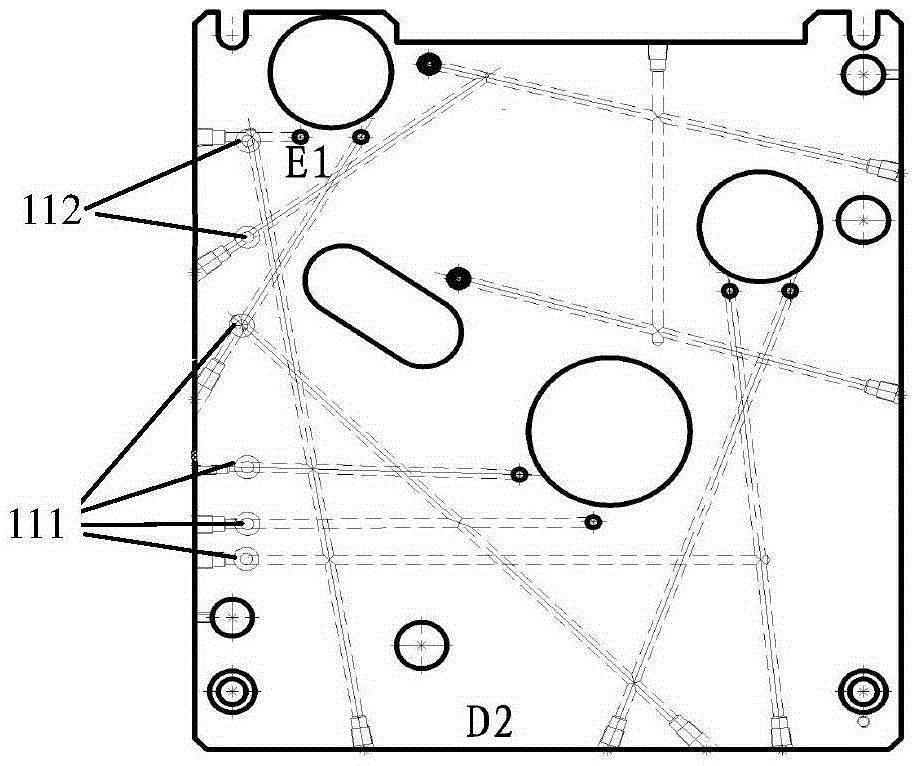
[0041] In addition, if figure 2 As shown, the detachable clamping plate 110 is also provided with a number of oil holes 111 and a number of air holes 112, which are respectively connected to a plurality of oil passages and air passages in the detachable clamping plate 110 for lubricating the device. A...

Embodiment 2

[0048] A split-type clamp includes: a detachable clamping mechanism, a carrying mechanism, and a positioning device. The detachable clamping mechanism is used for setting workpiece clamping parts; the bearing mechanism is provided with at least one mounting part, and the mounting part is used for carrying the detachable clamping mechanism. The positioning device is used for positioning the detachable clamping mechanism on the mounting part.

[0049] To sum up, the split fixture and clamping device proposed by the present invention can reduce the weight of the fixture and improve the convenience and safety of disassembly and assembly. When different workpieces need to be processed on the assembly line, only different types of detachable clamping plates need to be replaced, which makes the replacement of parts lightweight, reduces the risk of handling, saves replacement time, and indirectly improves processing efficiency. The versatility of the clamping device is also increased...


PUM


Abstract

The invention discloses a split clamp and clamping boards. The split clamp comprises a detachable clamping mechanism, a bearing mechanism and a positioning device, wherein the detachable clamping mechanism is provided with a workpiece clamping piece; the bearing mechanism is provided with at least one mounting part which is used for bearing the detachable clamping mechanism; and the positioning device is used for positioning the detachable clamping mechanism onto the mounting parts. According to the split clamp and the clamping boards, the weight of the clamp can be reduced, and assembling and disassembling convenience and safety can be improved. When different workpieces need to be machined on the assembly line, it is only needed to replace the detachable clamping boards with detachable clamping boards of different types. In this way, component replacement is easy, carrying danger is reduced, the replacement time is shortened, and machining efficiency is improved indirectly. Various different workpieces can be machined on one processing line by replacing the detachable clamping boards with detachable clamping boards of different types, and accordingly the universality of the clamping equipment is improved.

Description

technical field [0001] The invention belongs to the technical field of mechanical devices, and relates to a clamp, in particular to a split-type clamp; at the same time, the invention also relates to a clamping device including the above-mentioned clamp. Background technique [0002] A fixture is a device used to fix the workpiece to be processed in the process of mechanical manufacturing so that it occupies the correct position for construction or inspection. [0003] In the current parts processing process, especially in the machining process of light aluminum alloy auto parts, because it is usually mass-produced, its processing line is generally a dedicated assembly line. At present, the requirements for machining accuracy of auto parts are increasing day by day, and consequently, the requirements for the accuracy of jigs and clamping equipment are also getting higher and higher. [0004] In order to ensure the accuracy of the equipment, manufacturers usually use four-ax...

Claims


Application Information

Patent Timeline
IPC IPC(8): B25B11/00B23Q3/00
CPCB25B11/00B23Q3/00
Inventor 邹明慧施雄常世国朱宝
Owner MINO PRECISION DIE CASTING SHANGHAI CO LTD
Why Eureka
Try Eureka