Bottle making machine and rotary table driving device thereof

A driving device and bottle-making machine technology, applied in manufacturing tools, glass manufacturing equipment, glass re-molding, etc., can solve the problems of complex structure of the lifting mechanism, affecting the accuracy of glass bottles, deformation of vertical bearing seats, etc., and achieve relative rotation. The effect of flexibility, simple structure and improved stress condition

Active Publication Date: 2016-01-27
TRIUMPH JUNHENG CO LTD
View PDF5 Cites 7 Cited by
  • Summary
  • Abstract
  • Description
  • Claims
  • Application Information

AI Technical Summary

Problems solved by technology

[0004] In practice, the applicant's researchers found that there are at least the following problems: 1). Due to the needs of the production process, the height of the turntable and the corresponding parts of part A is higher than that of part B, so the platen of the fuselage needs to be There is a vertical bearing seat (called the support sleeve in CN103539335A) for installing the turntable of part A and the large gear of part A, etc., and because the whole bottle making machine is in a high temperature environment, it is vertical The strength or rigidity of the bearing seat needs to be additionally strengthened, otherwise the vertical bearing seat is easy to deform under the condition of high temperature and vibration, which will affect the accuracy of the glass bottle; 2). Due to the needs of the production process, the turntable and the corresponding The height of the parts needs to be adjusted, and the transmission structure provided in the aforementioned technical solution is complicated, and the structure of the lifting mechanism is complicated

Method used


Image

  • Bottle making machine and rotary table driving device thereof
  • Bottle making machine and rotary table driving device thereof
  • Bottle making machine and rotary table driving device thereof

Examples


Embodiment Construction

[0050] In order to enable those skilled in the art to better understand the various technical solutions involved in the present invention, the present invention will be further described in detail below in conjunction with the accompanying drawings and specific embodiments. It should be noted that, in the case of no conflict, the embodiments in this application and the specific technical features described in the embodiments can be combined in any suitable way; The possible combinations are not further described, as long as they do not violate the idea of ​​the present invention, they should also be regarded as the content disclosed in the present invention.

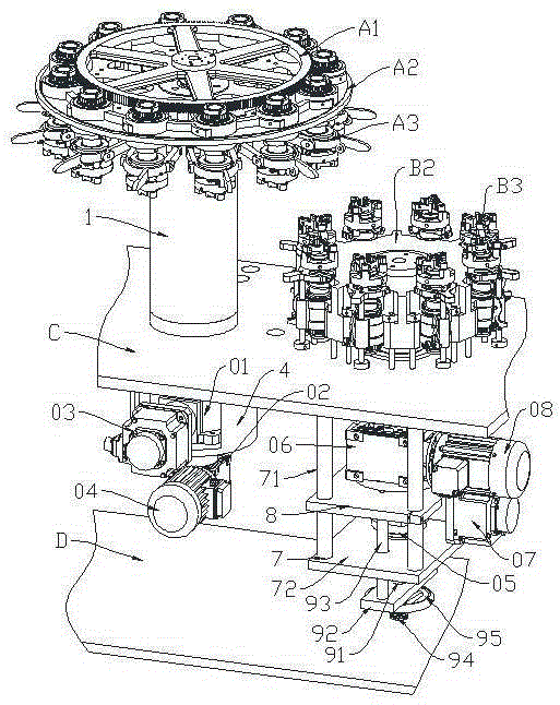
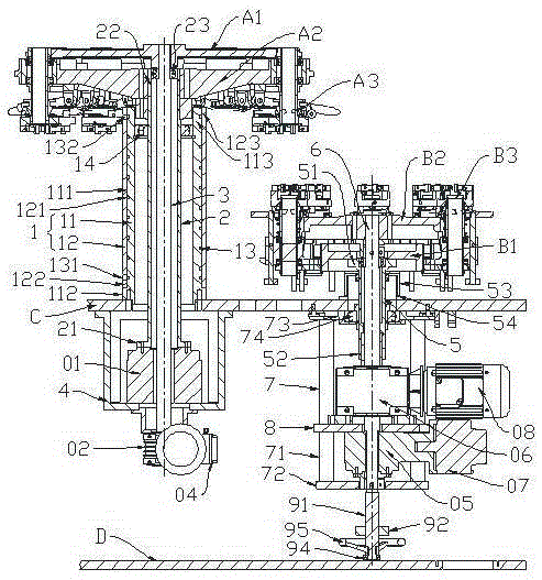
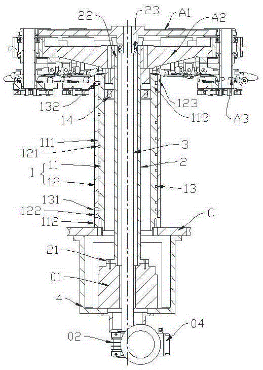
[0051] Such as figure 1 , figure 2 , image 3 and Figure 4 as shown, figure 1 It is a schematic diagram of the three-dimensional structure principle of the turntable drive device provided by a specific embodiment of the present invention; figure 2 figure 1 Schematic diagram of the longitudinal section of the pro...


PUM


Abstract

The invention discloses a rotary table driving device for a bottle making machine. The rotary table driving device comprises a part A rotary table driving device arranged on a bedplate, and / or a part B rotary table driving device arranged on the bedplate. The part A rotary table driving device comprises a bearing pedestal, a rotary table hollow shaft and a rack wheel spindle which are arranged above the bedplate, as well as a mounting seat mounted below the bedplate, wherein a first rotary platform is arranged in the mounting seat and driven by a first servo motor, and a first speed reducer is arranged below the mounting seat; the lower end of the rotary table hollow shaft is mounted on the first rotary platform; the lower end of the rack wheel spindle is mounted on an output shaft of the first speed reducer; the bearing pedestal comprises a support cylinder and an outer cylinder sleeve; a coolant passage is arranged on the outer edge of the support cylinder which is matched with the outer cylinder sleeve, and is distributed from bottom to top along a helical line; a lower connecting port and an upper connecting port of the coolant passage are respectively arranged at the lower part and the upper part of the outer cylinder sleeve. The rotary table driving device has the advantages of simplicity in structure, high convenience in operation, and higher stability and precision. The invention further provides the bottle making machine employing the rotary table driving device.

Description

technical field [0001] This application relates to the technical field of glass bottle preparation, in particular to a turntable drive device mainly used in bottle making machines. In the bottle making system, the turntable drive device includes A part turntable drive device and / or B part turntable drive device , mainly used to install and drive the large gear of part A and the turntable of part A and / or install and drive the large gear of part B and the turntable of part B. [0002] In addition, the present application also relates to a bottle making machine using the above-mentioned turntable driving device. Background technique [0003] Existing vertical bottle-making machines that use glass tubes to make glass bottles, such as vertical bottle-making machines for producing vials, generally include a fuselage, A and B parts installed on the fuselage, and other corresponding parts. part. For example, the Chinese invention patent application whose application publication n...

Claims


Application Information

Patent Timeline
IPC IPC(8): C03B23/045
Inventor 阳年生金清阳汪凯波
Owner TRIUMPH JUNHENG CO LTD
Why Eureka
Try Eureka