
Heat exchange unit and method for integrating absorption heat pump and electric heat pump

An absorption heat pump and heat exchange unit technology, applied in the energy field, can solve problems such as difficulty in meeting design requirements, insufficient heating capacity, and poor system economy.

Active Publication Date: 2018-01-05
BEIJING GAS & HEATING ENG DESIGN INST
View PDF9 Cites 2 Cited by
  • Summary
  • Abstract
  • Description
  • Claims
  • Application Information

AI Technical Summary

Problems solved by technology

In order to increase the heating area, a hot water-driven absorption heat exchange unit has appeared. Due to the limitation of the insulation material of the heating pipe network, the temperature of the hot water cannot be very high (less than 130°C), and the hot water transported by the primary network It is often lower than 125°C, resulting in low water temperature entering the generator of the absorption heat exchange unit, resulting in insufficient driving force of the absorption heat exchange unit. Therefore, it is difficult to reduce the return water temperature of the primary network to 35°C, and it is impossible to really increase the primary water temperature. The temperature difference between network supply and return water makes the heating capacity insufficient
Due to the high return water temperature of the primary network, after the primary side return water is transported to the heat source, it cannot effectively recover the waste heat of the heat source, resulting in poor economic efficiency of the entire system, and it is difficult to meet the design requirements

Method used


Image

  • Heat exchange unit and method for integrating absorption heat pump and electric heat pump
  • Heat exchange unit and method for integrating absorption heat pump and electric heat pump
  • Heat exchange unit and method for integrating absorption heat pump and electric heat pump

Examples


Embodiment Construction

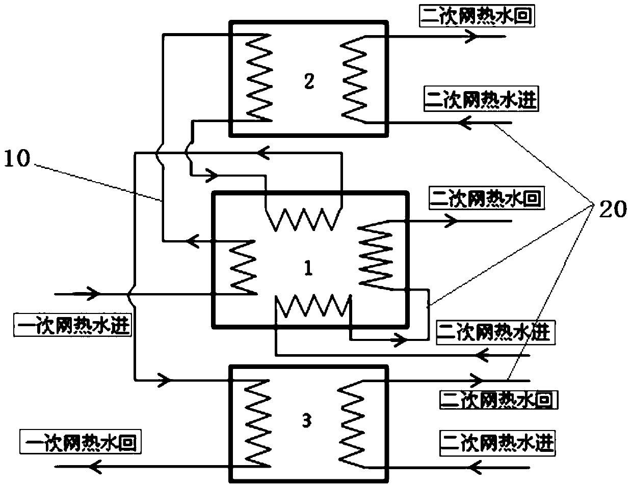
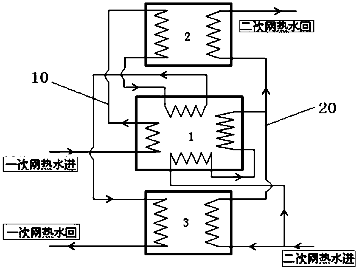
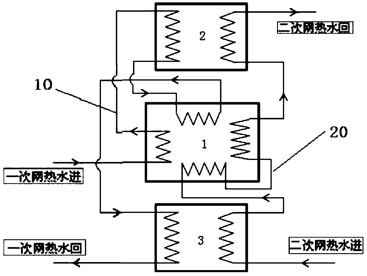
[0065] see Figure 1 to Figure 8 As shown, the present invention provides a heat exchange system consisting of an absorption heat pump 1, a water-water heat exchanger 2, an electric heat pump 3, and pipeline accessories (including primary side pipelines, secondary side pipelines and accessories), etc. As for the unit, one or more of the absorption heat pump 1, water-water heat exchanger 2 and electric heat pump 3 can be used.

[0066] The water system of the heat exchange unit is divided into two parts: the primary side pipeline and the secondary side pipeline, see Figure 1 to Figure 7 As shown, in each embodiment, the primary side pipelines 10 are connected in series step by step. figure 1 , Figure 5 and Figure 6 Three representative examples are shown:

[0067] Such as figure 1 As shown, the hot water on the primary side (inlet water from the primary network) passes through the generator of the absorption heat pump, the water-water heat exchanger, the evaporator of t...


PUM


Abstract

The invention discloses a heat exchange unit and method for integrating an absorption heat pump and an electric heat pump. The heat exchange unit is composed of an absorption heat pump unit, a water-water heat exchanger, an electric heat pump unit and various connecting pipelines and accessories. A waterway system of the connecting pipelines comprises primary side pipelines and secondary side pipelines, the primary side pipelines are sequentially connected in series, and hot water of the primary side pipelines sequentially passes through a generator of the absorption heat pump, the water-water heat exchanger, an evaporator of the absorption heat pump and an evaporator of the electric heat pump. Hot water of the secondary side pipelines can pass through a condenser of the electric heat pump, an absorber and a condenser of the absorption heat pump and the water-water heat exchanger in various manners. Heat of the hot water can be utilized in a gradient manner, and therefore the temperature difference between supplied water and return water of primary side hot water is greatly increased, and the heat supply capacity of a pipe network is improved. Due to the fact that the output water temperature of the primary side outlet heat exchange unit is lower than secondary side input water temperature, the low primary network return water temperature can be used for recycling low-grade waste heat of a heat source.

Description

technical field [0001] The invention relates to a heat exchange unit for heating and hot water supply and a method for realizing heat exchange by using it, in particular to an integrated absorption heat pump and an electric heat pump that can increase the temperature difference between the primary network hot water supply and return water. A large heat exchange device belongs to the technical field of energy. Background technique [0002] As the scale of cities in our country continues to increase, the scale of central heating in northern cities in winter continues to increase, and the heating pipe network continues to extend and increase capacity. In order to increase the heating area, a hot water-driven absorption heat exchange unit has appeared. Due to the limitation of the insulation material of the heating pipe network, the temperature of the hot water cannot be very high (less than 130°C), and the hot water transported by the primary network It is often lower than 125...

Claims


Application Information

Patent Timeline
Patent Type & Authority Patents(China)
IPC IPC(8): F24D3/10F24D3/18
Inventor 姜云涛
Owner BEIJING GAS & HEATING ENG DESIGN INST
Learn More