
Evaporative cooling system and operation method thereof

A technology for evaporative cooling and absorption of solutions, which is applied in air conditioning systems, heating methods, household heating, etc., can solve problems such as high energy consumption and cost, effective utilization, and lack of economically feasible utilization technologies, so as to reduce energy consumption, The effect of reducing production costs

Pending Publication Date: 2021-11-19
BEIJING LIANLI ENERGY TECH CO LTD
View PDF0 Cites 0 Cited by
  • Summary
  • Abstract
  • Description
  • Claims
  • Application Information

AI Technical Summary

Problems solved by technology

[0002] Conventional evaporative coolers can only cool the process fluid to around 35-40°C due to the limitation of the external air humidity, that is, the wet bulb temperature, especially in the southern summer.
For the case where the process fluid needs to be cooled to a lower temperature, only a compression refrigeration system can be used for secondary cooling, and the energy consumption and cost are high
[0003] On the other hand, industrial fields that require process fluid cooling often emit a large amount of low-temperature waste heat, but cannot be effectively utilized due to the lack of economically feasible utilization technologies

Method used


Image

  • Evaporative cooling system and operation method thereof
  • Evaporative cooling system and operation method thereof
  • Evaporative cooling system and operation method thereof

Examples


Embodiment 1

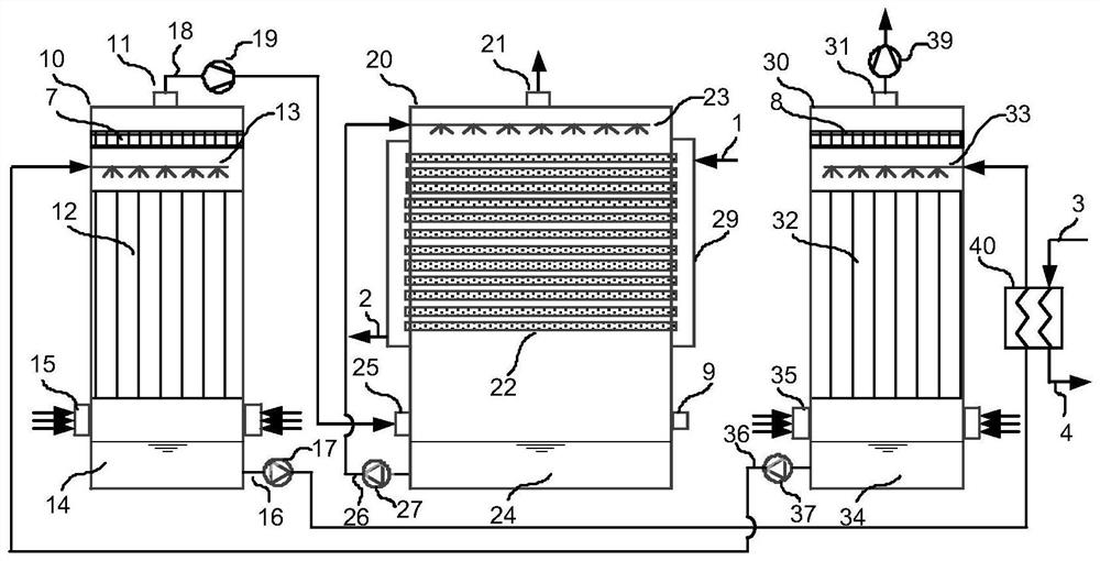
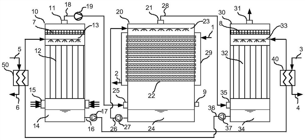
[0126] This embodiment provides an evaporative cooling system, see image 3 , the material of the air dehumidification tower 10 is ordinary carbon steel, its length and width are 4.5m, and the total height is 3.3m. The concentrated absorption solution spray mechanism 13 is composed of a spray main pipe and a nozzle. The height of the layer 12 is 2.5m, filled with polypropylene plastic Pall rings, the bottom of the air dehumidification tower 10 is used as a dilute absorption solution collection box 14, its height is 0.3m, and the first liquid collector 7 is composed of multi-layer 304 stainless steel wire mesh , its height is 0.1m; evaporative cooling device 20 is common carbon steel, its length and width are 4.5m, total height 3.3m, the heat transfer tube of heat transfer tube bundle 22 is oval heat transfer tube, and its material is common carbon steel, The absorption solution regeneration tower 30 is made of ordinary carbon steel, its length and width are 4.5m, and its total...

Embodiment 2

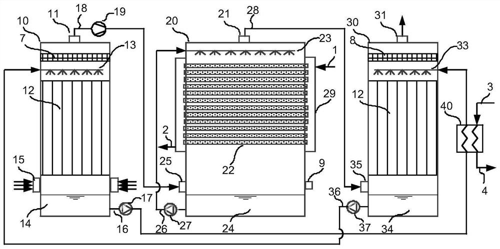
[0132] This embodiment provides an evaporative cooling system, see Figure 8 , The difference between this embodiment and Embodiment 1 is that the total height of the evaporative cooling device 20 is 4.4m, wherein the third packing layer 42 has a height of 1m and is filled with polypropylene plastic Pall rings; the second air fan 39 adopts a stainless steel shaft Flow fan.

[0133] For the operating method of the evaporative cooling system of this embodiment, see Figure 8 , including the following steps:

[0134] S1. Air dehumidification process: In the air dehumidification tower 10, the air that enters through the first air inlet 15 is mixed with the concentrated absorption solution sprayed by the concentrated absorption solution spraying device 13 in the air dehumidification tower 10. Countercurrent contact is carried out in the first packing layer 12 mentioned above, and the described concentrated absorption solution absorbs the moisture in the air to form a dilute absor...


PUM


Abstract

The invention relates to an evaporative cooling system and an operation method thereof. The system comprises an air dehumidification tower, an evaporative cooling device and an absorption solution regeneration tower, a first filler layer, a concentrated absorption solution spraying device and a diluted absorption solution collecting box are arranged in the air dehumidification tower, a first air introduction port is formed between the first filler layer and the diluted absorption solution collecting box, the evaporative cooling device comprises a water spraying device, a heat transfer tube bundle, a process fluid introduction pipeline, a process fluid introduction pipeline, a water collecting tank, a dry air introduction port, a wet air introduction port and a spraying water circulating pipeline, and a second filler layer, a dilute absorption solution spraying device and a concentrated absorption solution collecting box are arranged in the absorption solution regeneration tower. According to the system, the air dehumidification tower is arranged to dry air, the dry air is supplied to the evaporative cooling device to cool the process fluid, the cooling temperature which the process fluid can reach is substantially reduced, and the effects of energy conservation, emission reduction and cost reduction are achieved.

Description

technical field [0001] The invention relates to the technical field of thermal energy engineering, in particular to an evaporative cooling system and an operating method thereof, in particular to an evaporative cooling system utilizing industrial low-temperature waste heat and waste heat of a process fluid and an operating method thereof. Background technique [0002] Conventional evaporative coolers are limited by the humidity of the outside air, that is, the wet bulb temperature, especially in summer in the south, and usually can only cool the process fluid to around 35-40°C. For the case where the process fluid needs to be cooled to a lower temperature, only a compression refrigeration system can be used for secondary cooling, and the energy consumption and cost are relatively high. [0003] On the other hand, industrial fields that require process fluid cooling often emit a large amount of low-temperature waste heat, but cannot be effectively utilized due to the lack of ...

Claims


Application Information

Patent Timeline
Patent Type & Authority Applications(China)
IPC IPC(8): F24F5/00F24F3/14F24F13/30
CPCF24F5/0035F24F3/14F24F13/30F24F2003/1458Y02P80/10
Inventor 苏庆泉
Owner BEIJING LIANLI ENERGY TECH CO LTD
Learn More