Hot water apparatus and failure notification method for hot water apparatus

A hot water device and notification technology are applied in the field of detecting the blockage of the water circuit in the hot water device, and can solve the problems of low heating capacity and blockage.

Active Publication Date: 2016-01-27
MITSUBISHI ELECTRIC CORP
View PDF6 Cites 4 Cited by
  • Summary
  • Abstract
  • Description
  • Claims
  • Application Information

AI Technical Summary

Problems solved by technology

Therefore, even when clogging does not occur, if the heating capacity

Method used


Image

  • Hot water apparatus and failure notification method for hot water apparatus
  • Hot water apparatus and failure notification method for hot water apparatus
  • Hot water apparatus and failure notification method for hot water apparatus

Examples


Embodiment approach 1

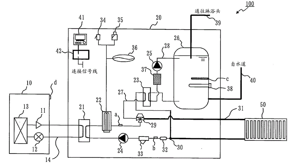
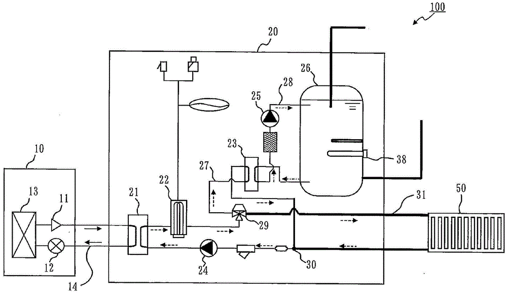
[0024] figure 1 It is a configuration diagram of the hot water device 100 according to Embodiment 1.

[0025] The hot water device 100 includes a heat pump device 10 (an example of a heat source device), a water heater 20 , and a heating device 50 .

[0026] The heat pump device 10 includes a compressor 11 , an expansion valve 12 , and a heat exchanger 13 .

[0027] The water heater 20 includes a heat exchanger 21, a heater 22, a heat exchanger 23, a pump 24, a pump 25, a tank 26, and the like.

[0028] The compressor 11 , the heat exchanger 21 , the expansion valve 12 , and the heat exchanger 13 are sequentially connected by pipes to constitute a refrigerant circuit 14 in which a refrigerant circulates.

[0029] The heat exchanger 21 , the heater 22 , the heat exchanger 23 , and the pump 24 are sequentially connected by pipes to constitute a primary water circuit 27 (an example of a fluid circuit) for supplying and circulating water. Moreover, the heat exchanger 23, the pu...

Embodiment approach 2

[0076] In Embodiment 2, the control when the secondary water circuit 28 is clogged will be described.

[0077] In Embodiment 2, the description of the same parts as Embodiment 1 is omitted, and the parts different from Embodiment 1 will be described.

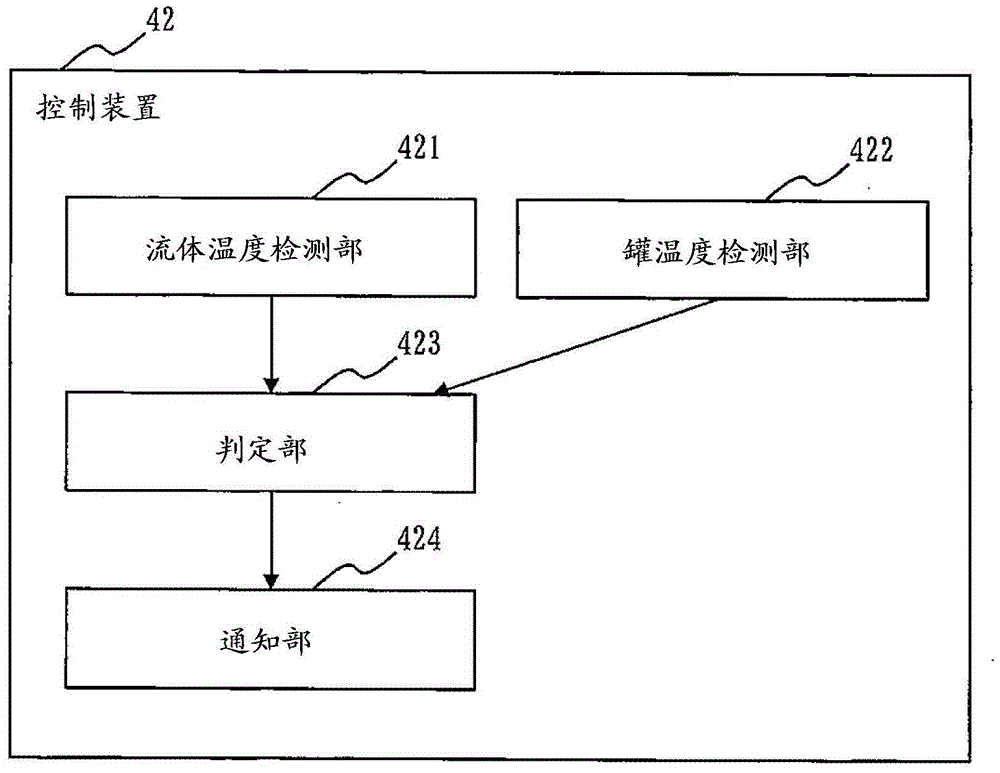
[0078] In Embodiment 1, when it is determined that the inflow temperature is not less than the first threshold and the tank temperature is not more than the second threshold, the user is notified that the secondary water circuit 28 is clogged. However, even if the clogging of the secondary water circuit 28 is notified, since the scale trapping device 37 and the heat exchanger 23 cannot be replaced immediately, there is a possibility that the hot water device 100 will be operated in a clogged state during this period of time. continue to operate.

[0079] Therefore, in Embodiment 2, when it is determined that the inflow temperature is equal to or greater than the first threshold and the tank temperature is equal to or less than ...


PUM


Abstract

An indirect-heating hot water apparatus is designed to correctly detect clogging in a secondary water circuit at low costs. A hot water apparatus 100 is provided with: a primary water circuit 27 in which water heated by absorbing heat from a refrigerant at a heat exchanger 21 circulates; a secondary water circuit 28 connected to the primary water circuit 27 via a heat exchanger 23, in which water circulates; and a tank 26 connected to the secondary water circuit 28, in which the water circulating in the secondary water circuit 28 is stored. The hot water apparatus 100 detects the temperature of the water circulating in the primary water circuit 27 and the temperature of the water stored in the tank 26. When the temperature of the water circulating in the primary water circuit 27 is at or above a first threshold and the temperature of the water stored in the tank 26 is at or below a second threshold, the hot water apparatus 100 issues a notification indicating that the secondary water circuit 28 is clogged.

Description

technical field [0001] The present invention relates to techniques for detecting clogging of water circuits in hot water installations. Background technique [0002] There are direct heating hot water device and indirect heating hot water device in the hot water device, wherein, the direct heating hot water device uses the heat source device to heat the water circulating in the water circuit, and the heated water circuit The circulating water is stored in the tank, the indirect heating hot water device uses the heat source device to heat the water circulating in the primary water circuit, uses the water circulating in the primary water circuit to heat the water circulating in the secondary water circuit, and The water circulated in the heated secondary water circuit is stored in tanks. [0003] Among the indirect heating water heaters, there is also a water heater of a fluid circuit in which a fluid such as brine other than supply water circulates in the primary water circu...

Claims


Application Information

Patent Timeline
IPC IPC(8): F24D3/18F24D19/10
CPCF24D19/0092F24H4/04F24H9/2007F24D19/1039F24D19/1066F24D19/1051F24H1/208F24D19/1072G08B21/182
Inventor 南迫博和竹山庆
Owner MITSUBISHI ELECTRIC CORP
Why Eureka
Try Eureka