
A flash memory control chip

A flash memory control, chip technology, applied in the field of electronic information

Active Publication Date: 2019-07-30
SHENZHEN CHIPSBANK TECH
View PDF4 Cites 0 Cited by
  • Summary
  • Abstract
  • Description
  • Claims
  • Application Information

AI Technical Summary

Problems solved by technology

[0003] With the emergence of more and more new types of flash memory with deep submicron technology, the boost circuit inside the flash has become an increasingly fragile part of the flash, and the proportion of the entire flash that cannot work due to its problems is also increasing. It is getting higher and higher, and with the increase of flash usage time, increasing the output voltage of the booster circuit has a very direct effect on extending the life of the flash, but the fixed output voltage inside the flash will lead to more and more flash units premature end of life

Method used


Image

  • A flash memory control chip
  • A flash memory control chip

Examples


Embodiment Construction

[0014] The following will clearly and completely describe the technical solutions in the embodiments of the present invention with reference to the accompanying drawings in the embodiments of the present invention. Obviously, the described embodiments are only some, not all, embodiments of the present invention. Based on the embodiments of the present invention, all other embodiments obtained by persons of ordinary skill in the art without making creative efforts belong to the protection scope of the present invention.

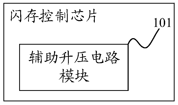
[0015] The invention provides a flash memory control chip, figure 1 A schematic structural diagram of a flash memory control chip of the present invention is shown, including:

[0016] The auxiliary boost circuit module 101 is an auxiliary boost circuit module, which is used to adjust and determine the target voltage value that needs to be provided to the flash memory control chip according to the usage time of the flash memory control chip, and use its own ou...


PUM


Abstract

The invention discloses a flash memory control chip. The flash memory control chip comprises an auxiliary boost circuit module, which is used for regulating and determining the target voltage value which is required to be supplied to the flash memory control chip according to the service time of the flash memory control chip, and boosting the flash memory control chip by using self output voltage according to the target voltage value. The auxiliary boost circuit module is added to the flash memory control chip, the failure of the flash memory control chip caused by the failure of the boosting circuit in the flash memory control chip is prevented, and the service life of the flash memory control chip is prolonged.

Description

technical field [0001] The invention relates to the field of electronic information, in particular to a flash memory control chip. Background technique [0002] Flash memory (Flash Memory, referred to as flash) is a long-life non-volatile (it can still maintain the stored data information in the case of power failure) memory. Data deletion is not in single byte units but in fixed The block is the unit, [0003] With the emergence of more and more new types of flash memory with deep submicron technology, the boost circuit inside the flash has become an increasingly fragile part of the flash, and the proportion of the entire flash that cannot work due to its problems is also increasing. It is getting higher and higher, and with the increase of flash usage time, increasing the output voltage of the booster circuit has a very direct effect on extending the life of the flash, but the fixed output voltage inside the flash will lead to more and more flash units premature end of l...

Claims


Application Information

Patent Timeline
Patent Type & Authority Patents(China)
IPC IPC(8): G11C16/30
Inventor 王玉明李华伟
Owner SHENZHEN CHIPSBANK TECH
Learn More