
Cable stripper

A stripper and cable technology, applied in the direction of dismantling/armored cable equipment, etc., can solve the problems of not being able to insert and strip, increase the amount of work, troublesome operation, etc., and achieve the effect of improving stripping efficiency and reducing friction

Inactive Publication Date: 2016-01-27
STATE GRID SHANDONG ELECTRIC POWER COMPANY WEIFANG POWER SUPPLY +1
View PDF7 Cites 18 Cited by
  • Summary
  • Abstract
  • Description
  • Claims
  • Application Information

AI Technical Summary

Problems solved by technology

However, for the old cables that have been laid in the pipeline, when it needs to be re-stripped and re-wired, due to the limitation of the pipeline space, the traditional wallpaper knife is difficult to hold and it is difficult to complete the stripping task
Because the protective pipeline cannot be damaged, the method often used at this time is to lay new cables, which not only increases the amount of work, but also causes waste.
[0003] The Chinese patent No. 201310447480.1 discloses a cable stripping knife. The stripping knife has a simple structure and can realize the function of cable stripping, but has the following disadvantages: 1. The stripping knife can only be inserted from the end of the cable. For peeling, it cannot be inserted and peeled from the place where the peeling is determined, and the flexibility of use is average; 2. The skinning knife is generally suitable for two people to use together, that is, one person pulls the wire, and the other pulls the peeling knife in the opposite direction. If one person If you use it, you can only pull the cable with one hand, and pull the skinning knife with the other hand. The operation is troublesome and inefficient, or you can fix the end of the cable in advance, and you can also operate it by one person. 3. The gap between the cutter head 5 and the cable guide wheel determines the thickness of the matched cable, but since the cutter head pressure rod 4 is not fixed, When pulling the cable guide, the change in the grip force of the arm holding the cable guide and the cutter head pressure bar 4 will affect the above-mentioned gap, and will also cause the scratches of the cutter head 5 on the cable sheath to be of different depths, which will affect the peeling effect; 4. Knife The relative fixation of the head 5 and the cutter head pressure bar 4 depends entirely on the tightening force in the vertical direction applied by the cutter head adjusting bolt nut 6, so when in use, the cutter head adjusting bolt nut 6 needs to be screwed very tightly, otherwise it will cause The cutter head 5 slips relative to the cutter head pressure rod 4, resulting in peeling failure. Therefore, there are requirements for the operator's operating strength; That is to say, the cable sheath can only be divided into two, but the cable sheath cannot be cut circularly from the initial cutting point. It must be completed with other auxiliary tools such as wallpaper knife or scissors.
In this patent, there are three blades on the head of the pliers, which can play the role of cutting the outer skin of the cable, but the cutting depth is completely controlled by the operator (palm). Once the operation is not good, it is easy to cut the cable core. , and the blade at the handle still has the hidden danger of cutting fingers, so the requirements for the operator are higher

Method used


Image

  • Cable stripper
  • Cable stripper
  • Cable stripper

Examples


Embodiment Construction

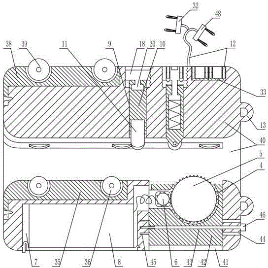
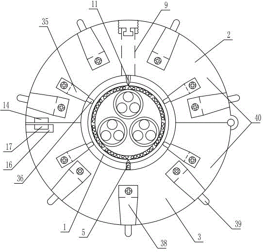
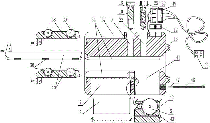
[0044] As shown in the figure, the cable stripper includes a sleeve 40 for covering the cable 1. The sleeve includes a main half pipe 2 and an auxiliary half pipe 3. One side of the main half pipe and the auxiliary half pipe are hinged together and the other side is locked by locking. The devices are locked together, and the side wall of the casing is provided with a power chamber 4 communicating with the inner cavity of the casing. The power chamber is installed with a power gear that is tightly fitted with the cable sheath and a motor 6 that drives the power gear 5 to rotate. A battery chamber 7 is provided, and a battery 8 for supplying power to the motor is installed in the battery chamber. A switch 12 for controlling the power supply of the motor is provided on the outer wall of the casing, and a blade chamber 9 is vertically arranged on the side wall of the casing. The cross section of the blade chamber It is a regular polygon, and the number of sides of the polygon is a ...


PUM


Abstract

The invention discloses a cable stripper. The cable stripper includes a main half tube and an auxiliary half tube which are locked together through a locking device so as to form a sleeve; a power gear which is in press fit with the outer sheath of a cable and a motor for driving the power gear to rotate are arranged in a power cavity of the sleeve; the outer wall of the sleeve is provided with a switch for controlling the on-off of the power source of the motor; the cross section of a blade cavity of the sleeve is a regular polygon; the edges of the polygon are an positive integer times of four; a blade handle is slidingly inserted in the blade cavity; a blade which can longitudinally cut the cable is fixedly arranged in the inner end of the blade handle; the outer section of the blade cavity is in threaded connection with a positioning device for axially positioning the blade handle; and an end portion of the sleeve is fixedly provided with a connecting ring. With the cable stripper adopted, axial longitudinally-cutting stripping and transverse annularly-cutting stripping can be both realized, and stripping can be initially performed on any portion of the cable, and cable stripping can be performed in a pipeline, and stripping depth can be adjusted. The cable stripper has the advantages of automatic stripping and time-saving and labor-saving operation.

Description

technical field [0001] The invention relates to a cable stripper. Background technique [0002] During the construction, maintenance and intelligent upgrading of substations, it is necessary to re-make terminal clips and re-wire all kinds of old wires and cables, or directly re-lay new cables. Whether it is wiring the old cable or wiring the new cable, the cable head needs to be stripped so that the cable cores can be allocated and connected. When stripping the cable sheath, a stripping knife or stripper is required. At present, there are not many practical stripping knives or stripping devices, so wallpaper knives are generally used to strip the cables on site. However, due to the smooth appearance of the cables, they are easy to slip during stripping, and it is easy to hurt the hands. Difficult to control, easy to cut the cable core. It is easier to strip the new cables that have not been laid or have just been laid, because the cables are completely exposed, and the st...

Claims


Application Information

Patent Timeline
Patent Type & Authority Applications(China)
IPC IPC(8): H02G1/12
Inventor 晋飞王雪蒂杨君仁吴金玉辛翠芹刘贯红杨坤马献丽管正弦王君安刘道林李世贤李玉志张建军林勇
Owner STATE GRID SHANDONG ELECTRIC POWER COMPANY WEIFANG POWER SUPPLY
Learn More