Voice coil motor possessing gravity compensation function
A voice coil motor, gravity compensation technology, applied in electrical components, electromechanical devices, etc., can solve the problems of increasing motor heating, no load gravity compensation function, etc., and achieve the effect of extending service life, conducive to heat dissipation, and small size
- Summary
- Abstract
- Description
- Claims
- Application Information
AI Technical Summary
Problems solved by technology
Method used
Image

Examples
Embodiment 1
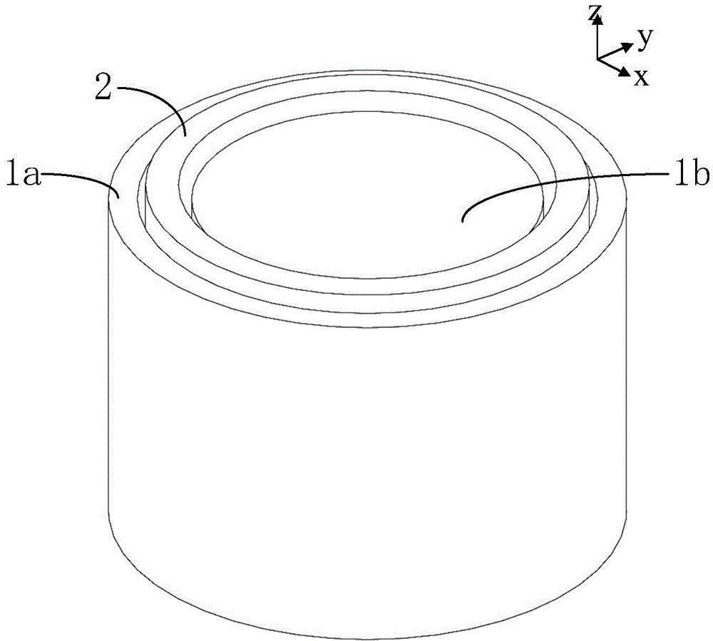
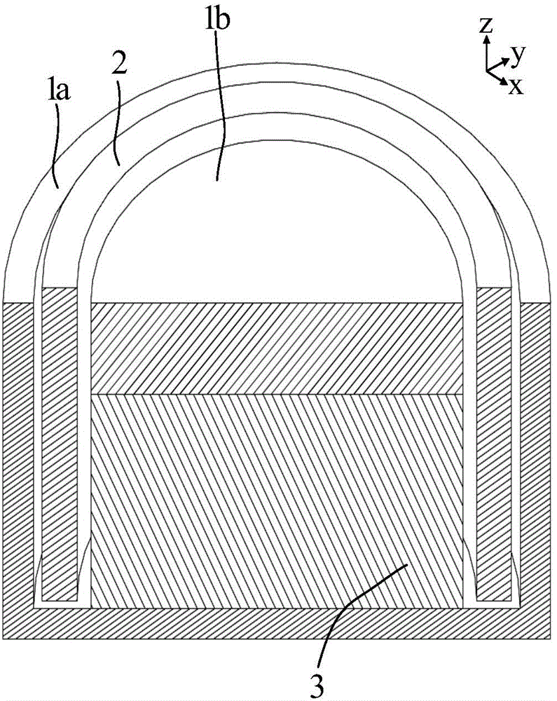
[0110] Please refer to Figure 4 to Figure 7 , the voice coil motor with gravity compensation function provided by the present invention includes: an external back iron, the external back iron is a cylindrical back iron or is composed of two plate-shaped back irons, and a cylindrical back iron 110 is used in this embodiment The magnetic steel assembly 130 placed in the cylindrical back iron 110; and the coil placed between the inner side of the cylindrical back iron 110 and the outer side of the magnetic steel assembly 130, the coil and the magnetic steel assembly 130 can move relative to each other. Specifically, the coils can be in one group or two groups. When the coils are in one group, the corresponding magnetic steel assembly includes a center back iron, a cylindrical shape sleeved on the center back iron Magnet, the position of the coil corresponds to the position of the cylindrical magnet; in this embodiment, the coils are two groups, and the two groups of coils are no...
Embodiment 2
[0123] Embodiment 2 preferably, please refer to Figure 11 The difference between this embodiment and Embodiment 1 is that: the center back iron 231 is provided with a cylindrical hole 241 that runs through the entire center back iron 231 along the axial direction of the voice coil motor, and the cylindrical hole 241 can be easily penetrated into Horizontal (x, y) limit guide posts, of course, the limit guide posts must be non-magnetic materials. Please focus on reference Figure 12 , adding the cylindrical hole 241 in the center back iron 231 will not block the magnetic circuit and still achieve the effect of gravity compensation.
Embodiment 3
[0125] Preferably, please refer to Figure 13 The difference between this embodiment and Embodiment 1 is that the magnetic steel assembly 330 includes a central magnet 331, two first back irons 332a, 332b, and two cylindrical magnets 333a, 333b with opposite magnetization directions. A first back iron 332a, 332b is fixedly connected to both ends of the center magnet 331, and the two cylindrical magnets 333a, 333b are sleeved on the outer sides of the two first back irons 332a, 332b respectively. The magnet 331, the two first back irons 332a, 332b and the two cylindrical magnets 333a, 333b are fixedly connected to each other to form a whole. Specifically, the positions of the two cylindrical magnets 333a, 333b correspond to the positions of the two sets of coils 320a, 320b one by one.
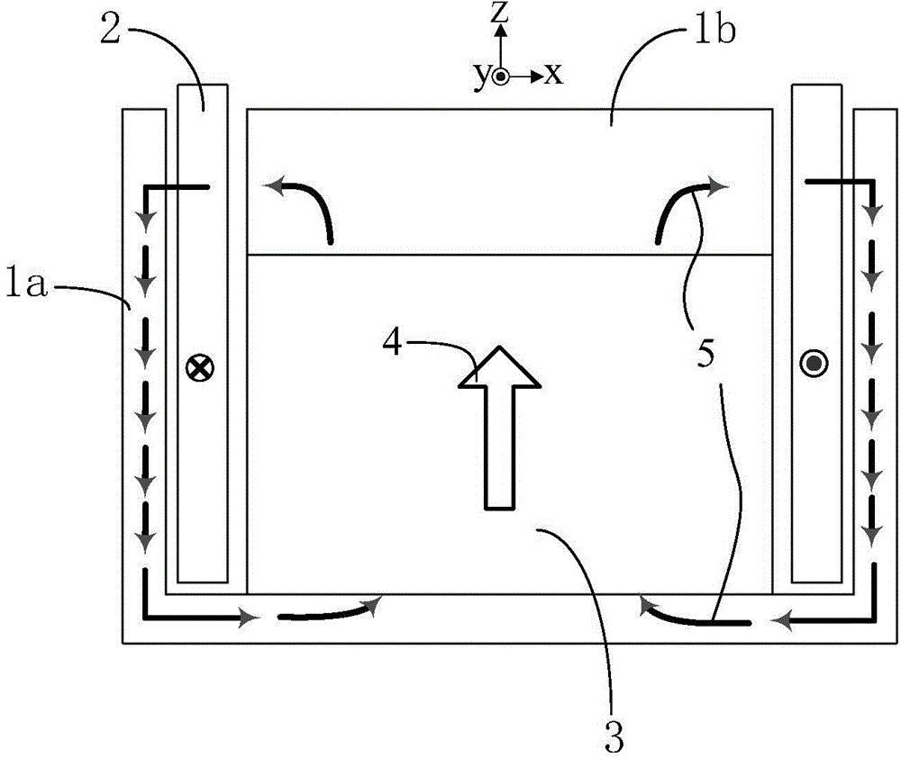
[0126] Please focus on reference Figure 14 , the thick arrow 340 in the figure represents the magnetization direction of the magnet, and the thin arrow 350 represents the direction of the mag...
PUM
 Abstract
Description
Claims
Application Information
 - R&D
- Intellectual Property
- Life Sciences
- Materials
- Tech Scout
- Unparalleled Data Quality
- Higher Quality Content
- 60% Fewer Hallucinations
Browse by: Latest US Patents, China's latest patents, Technical Efficacy Thesaurus, Application Domain, Technology Topic, Popular Technical Reports.
© 2025 PatSnap. All rights reserved.Legal|Privacy policy|Modern Slavery Act Transparency Statement|Sitemap|About US| Contact US: help@patsnap.com