Heat transfer management technology for mold tools

A tool and mold technology, applied in the field of temperature management of mold tools, can solve the problems of sudden fluid flow, harmful effects of mold tools and workpieces, etc., to achieve space-effective effects

Active Publication Date: 2018-01-12
SURFACE GENERATION
View PDF5 Cites 0 Cited by
  • Summary
  • Abstract
  • Description
  • Claims
  • Application Information

AI Technical Summary

Problems solved by technology

[0014] Additionally, the combined effect of waste heat from heating to cooling in the in-line heater and the need for increased fluid flow during the transfer creates a high temperature "kick" that can have detrimental effects on both the mold tooling and the workpiece

Method used

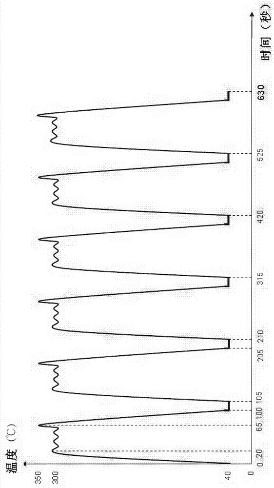
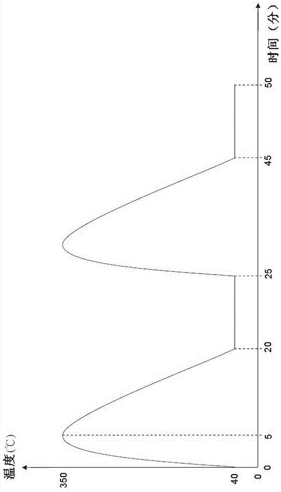
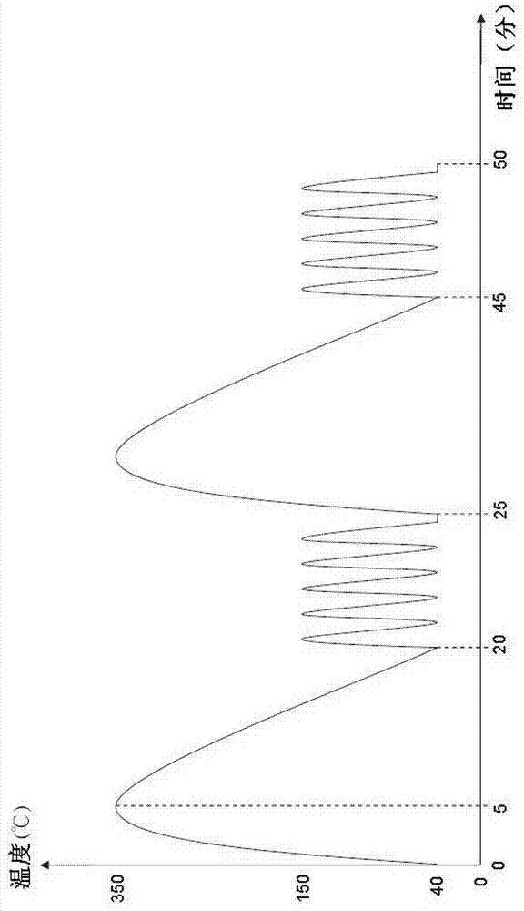

Image

  • Heat transfer management technology for mold tools
  • Heat transfer management technology for mold tools
  • Heat transfer management technology for mold tools

Examples


Embodiment Construction

[0050] Please refer to Figure 3a , the tool 100 includes a first layer 102 , a second layer 104 , a third layer 106 , and a support assembly 108 .

[0051] The first layer 102 includes a tool face 110 . The tool face 110 defines the shape of the workpiece to be formed, and in use is associated with an opposing tool (not shown). On the bottom surface of the tool face 110, a temperature control surface 112 as described below is defined.

[0052] The first layer 102 is surrounded by a peripheral wall 114 so as to define an enclosed volume. The first layer 102 defines a number of discrete chambers 118 bounded at a first end by a portion of the temperature control surface 112 and open at a second end 116 . The chamber 118 is separated by a chamber wall 120 extending from the temperature control surface 112 to the open end 116 . Likewise, the first layer 102 defines a honeycomb structure composed of a plurality of discrete cell-like chambers 118 .

[0053] The temperature cont...


PUM


Abstract

A tool system for molding an object comprising: a tool (100) having a tool surface (110) for forming an object, the tool surface (110) including a plurality of tool zones for directing heating or cooling A plurality of fluid flow paths (151, 152) for fluid flow to individual tool zones, a heating element including an in-line heater (150) for heating fluid passing through a respective heating fluid flow path, and a heating element including a cooling fluid flow path cooling means, the cooling fluid flow path bypasses the heating fluid flow path of the in-line heater.

Description

technical field [0001] The present invention relates to the temperature management of casting mold tools. More particularly, the invention relates to active power and flow management techniques for the temperature of casting mold tools heated and cooled by fluids. Background technique [0002] In particular, fluid heating technology for casting mold tools is known from the applicant's earlier published application No. WO 2011 / 048365. In this document, fluid-based and independently associated heating and cooling means to individual zones of a casting mold tool are described, while control means are designed to control the heating and cooling means to individually heat or cool these tool zones so that during the molding process At any given time, the heat transfer to and from the object to be molded is regulated at each tool zone. [0003] Such casting tools are generally used for two different purposes. [0004] The first type of mold tooling application is high volume ser...

Claims


Application Information

Patent Timeline
IPC IPC(8): B29C33/04
CPCB29C33/04B29C35/0294B29C35/16B29C2033/042B29C2035/1616
Inventor 本·哈尔福特
Owner SURFACE GENERATION
Why Eureka
Try Eureka