Oil-gas separating disc

A separation disc, oil and gas technology, used in separation methods, dispersed particle separation, oil fume removal, etc., can solve the problems of easy falling off, intercepting oil mist and unable to form sufficient adhesion, etc. powerful effect

Inactive Publication Date: 2016-02-03
浙江高水品炭科技有限公司
View PDF7 Cites 4 Cited by
  • Summary
  • Abstract
  • Description
  • Claims
  • Application Information

AI Technical Summary

Problems solved by technology

However, because the steel wire is wound in a radial shape, it cannot form sufficient adhesion when intercepting the oil mist, and it is easy to fall off at high speeds, and the

Method used


Image

  • Oil-gas separating disc
  • Oil-gas separating disc
  • Oil-gas separating disc

Examples


Embodiment 1

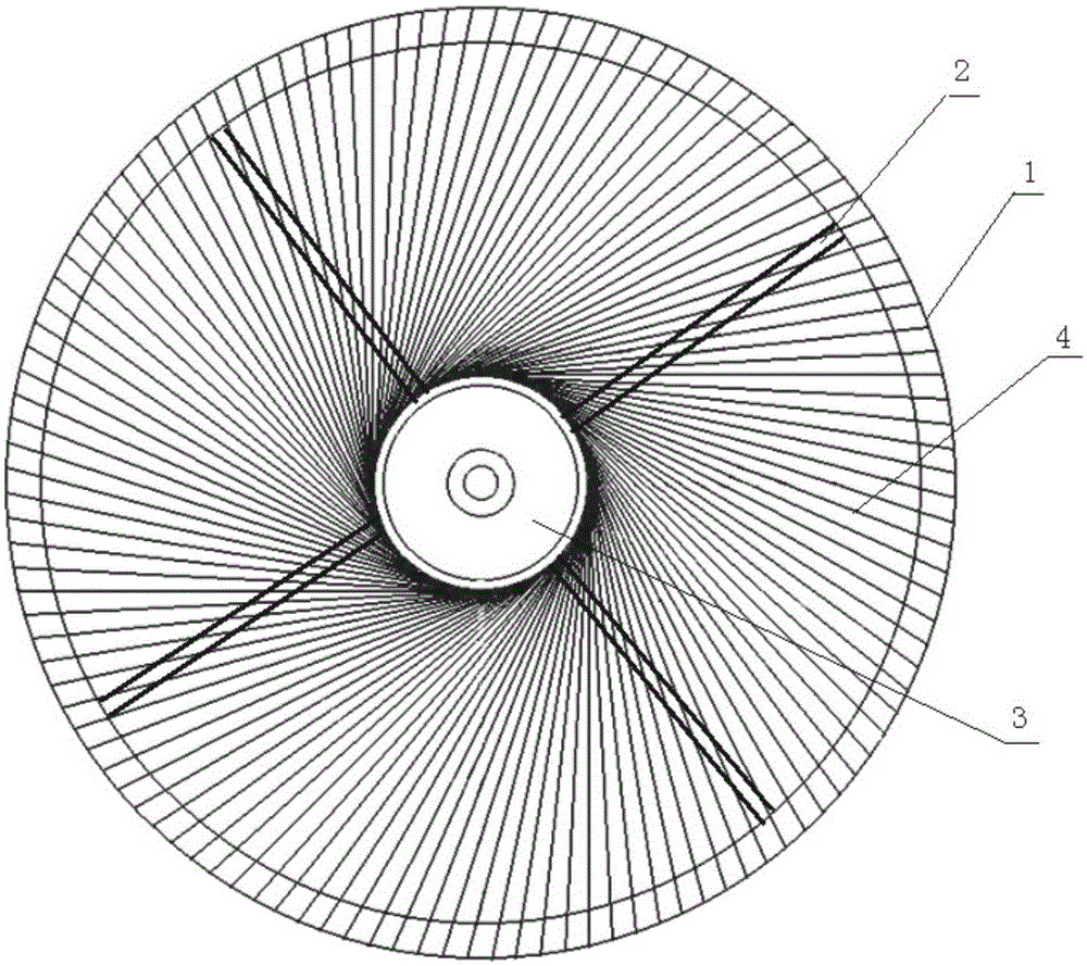
[0027] Embodiment 1. An oil-gas separation disc, comprising an outer rim 1 and an inner rim 3, the outer rim 1 and the inner rim 3 are connected by several uniformly and symmetrically arranged radial support ribs 2; the radial support ribs 2 The number is generally 4 to 8.

[0028] In the annular area between the outer rim 1 and the inner rim 3, two upper and lower layers of tangential radial filter screens 4 are arranged.

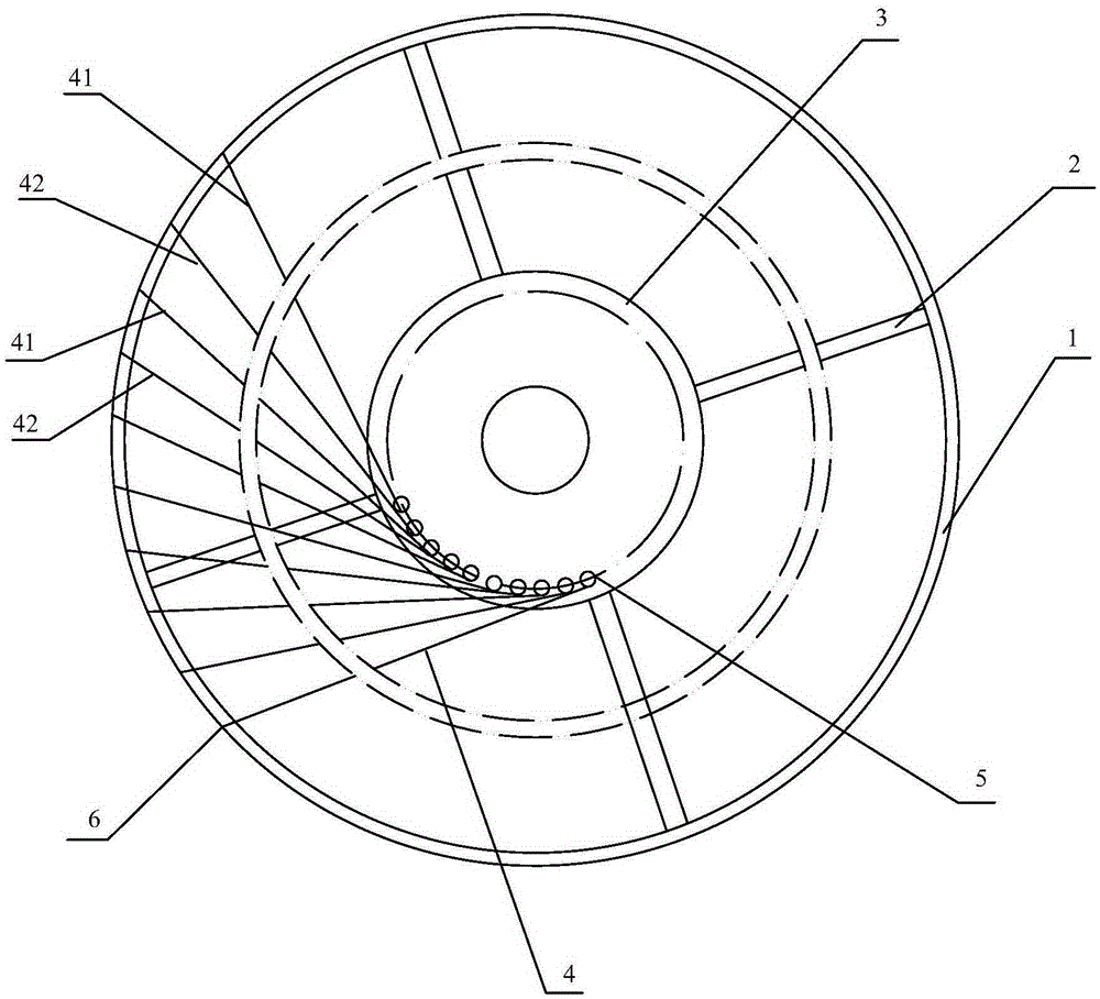
[0029] The structure of the tangent radial filter screen 4 of each layer is as follows: each mesh line on the tangent radial filter mesh 4 is the tangent line of the inner rim 3; ; That is, the combination of wires on the tangential radial filter screen 4 forms the tangential direction of the inner rim 3 .

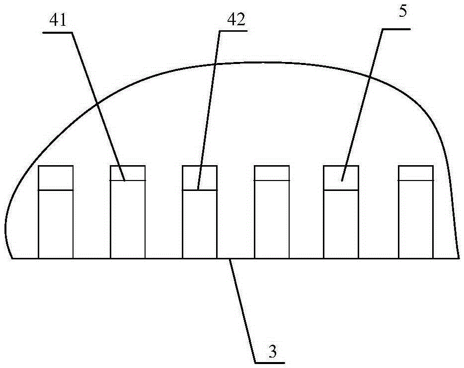
[0030] A number of fixed parts—cylindrical bosses 5 are evenly arranged along the outer circumference of the inner rim 3, and positioning parts corresponding to the cylindrical bosses 5 are arranged on the outer rim 1—grooves 6, tangential radial filt...


PUM

PropertyMeasurementUnit
Angleaaaaaaaaaa

Abstract

The invention discloses an oil-gas separating disc. The oil-gas separating disc comprises an outer rim (1) and an inner rim (3) which are coaxial. The outer rim (1) and the inner rim (3) are connected through a radial supporting rib (2). The annular area between the inner rim (3) and the outer rim (1) is provided with at least one tangent radial filter screen (4). Each screen wire on the tangent radial filter screen (4) is the tangent of the inner rim (3). The oil-gas separating disc is installed in a range hood, and therefore oil mist can be effectively intercepted, and oil mist emitted to the atmosphere together with gas flow is greatly reduced.

Description

technical field [0001] The invention relates to an oil and gas separation disc. Background technique [0002] The function of the range hood is to exhaust the oil, gas and oil mist to the outside, which will cause serious pollution to the environment and form a source of pollution. Therefore, it is necessary to install an oil-gas separation device on the range hood to achieve the purpose of intercepting the oil mist. [0003] The invention of 200910062096.3 "Radial Radial Rotating Filter Disc and Its Manufacturing Method" discloses a radial radial rotating filter disc, including an outer rim and an inner rim, and the outer rim and the inner rim are supported by radial The annular area between the outer rim and the inner rim is provided with a radial radial filter mesh that is woven by a filter mesh wire and uniformly distributed along the circumferential direction. The oil-gas separation device of this structure works in a high-speed rotation state. Because the oil-gas sep...

Claims


Application Information

Patent Timeline
IPC IPC(8): B01D46/10F24C15/20
Inventor 张成伟涂韬诲曾建新饶整
Owner 浙江高水品炭科技有限公司
Why Eureka
Try Eureka