
Cooling liquid recovery device integrating chip removal and circulation

A recovery device and cooling fluid technology, applied in metal processing machinery parts, maintenance and safety accessories, metal processing equipment, etc., can solve the problems of low cleaning efficiency of metal debris

Inactive Publication Date: 2016-02-03
SUZHOU RS TECH
View PDF9 Cites 10 Cited by
  • Summary
  • Abstract
  • Description
  • Claims
  • Application Information

AI Technical Summary

Problems solved by technology

[0005] In view of the deficiencies in the above-mentioned technologies, the purpose of the present invention is to provide a coolant recovery device integrating chip removal and circulation, to optimize and improve the existing coolant recovery device, and to ensure that the filtration accuracy is ensured as much as possible. Improve the filtration and cooling efficiency as much as possible, and at the same time solve the problem of low cleaning efficiency of metal debris in the current coolant recovery device, so as to maximize the working efficiency of the machine tool machining center

Method used


Image

  • Cooling liquid recovery device integrating chip removal and circulation
  • Cooling liquid recovery device integrating chip removal and circulation
  • Cooling liquid recovery device integrating chip removal and circulation

Examples


Embodiment approach

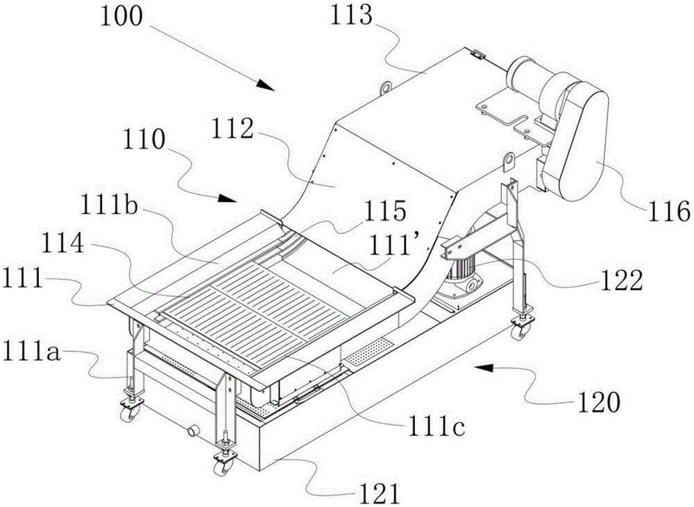
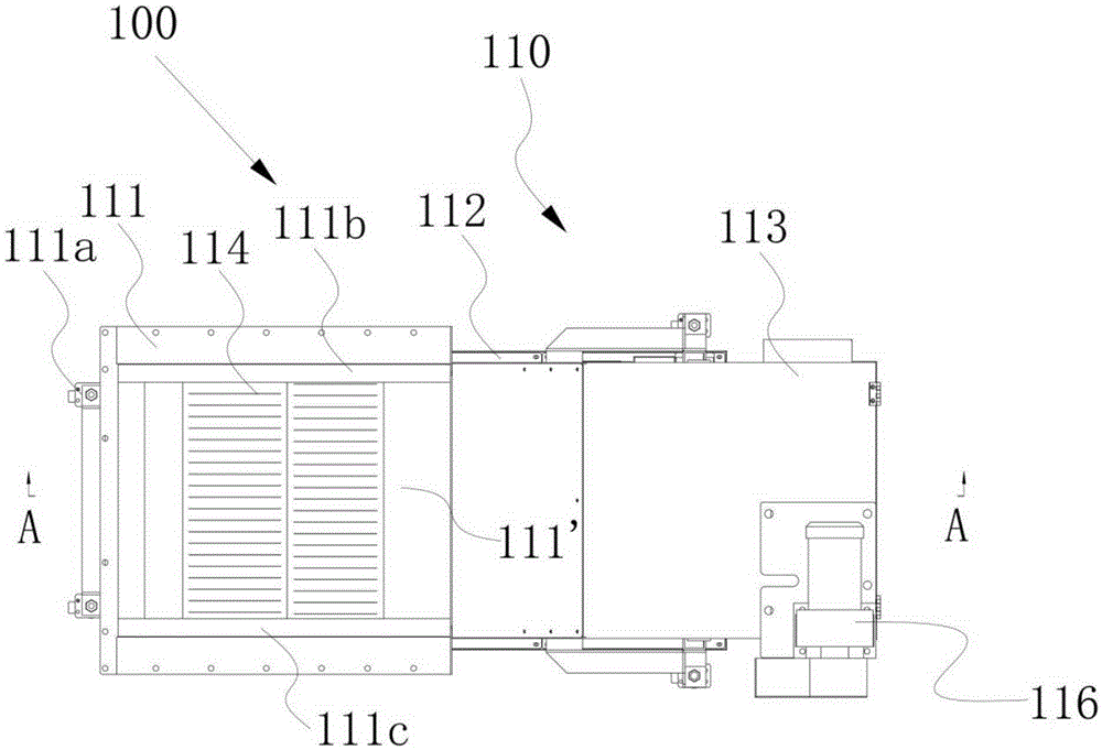
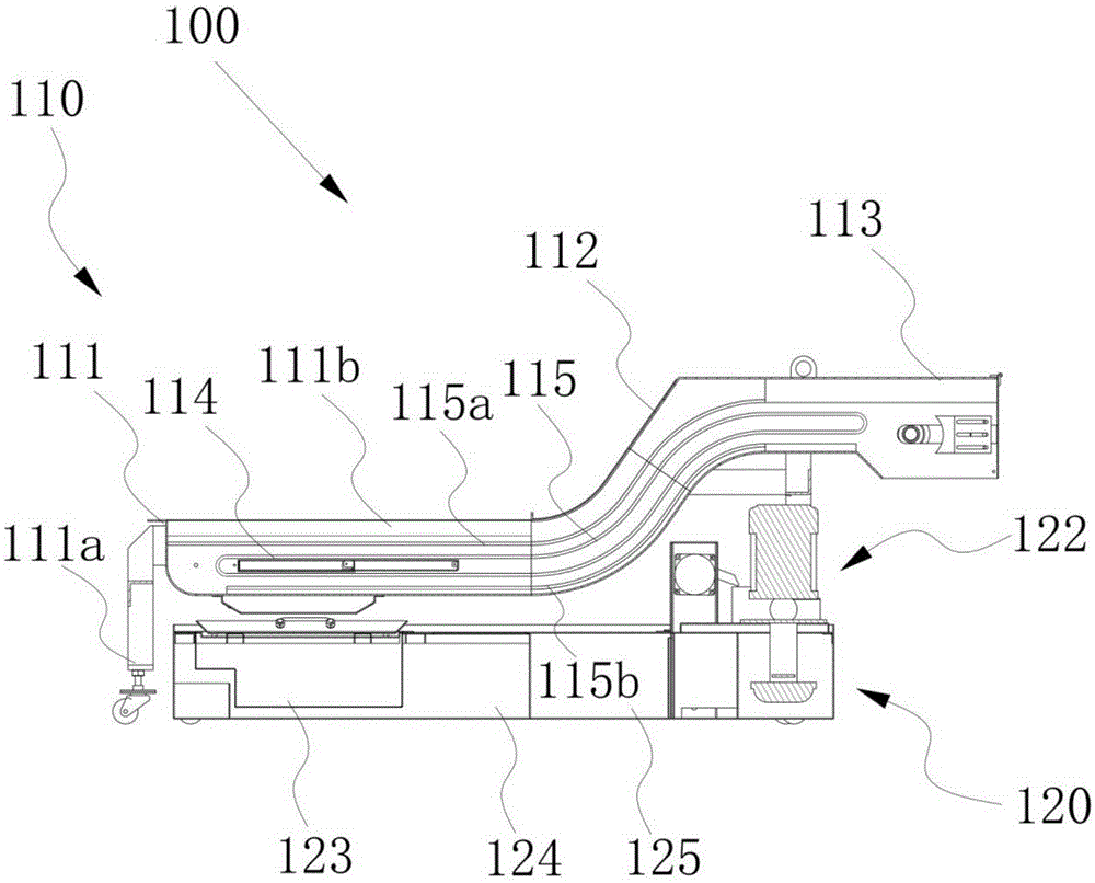
[0027] refer to Figure 4 The top of the coarse filter chamber 123 is covered with a coarse filter chamber cover plate with some water inlet holes, the top of the fine filter chamber 124 is covered with a fine filter chamber cover plate with some overflow holes, and the top of the cooling chamber 125 is provided with a circulating water pump 120 . As an implementation manner, the overflow hole is disposed on one side close to the coarse filtration chamber 123 .

[0028] Working principle: After the cooling dirty liquid mixed with metal debris is introduced from the opening 111' of the horizontal section 111, after the initial filtration by the primary filter plate 114, the metal debris with a larger geometric size remains on the surface of the primary filter plate 114 , and the cooling dirty liquid is discharged into the coarse filter chamber 123 of the coolant recovery box 120 located directly below the chip conveyor 110 through the drainage hole below the primary filter pla...


PUM


Abstract

The invention discloses a cooling liquid recovery device integrating chip removal and circulation. The cooling liquid recovery device comprises a cooling liquid recovery tank and a chip removal machine arranged over the cooling liquid recovery tank and used for removing cutting metal chips, wherein the chip removal machine comprises a hollow machine shell, a front conveying chain, a rear conveying chain and a chip removal driving motor, and the front conveying chain and the rear conveying chain are arranged on the front side and the rear side of the interior of the machine shell. The machine shell comprises a horizontal section, an ascending section, and a chip removal section, wherein the horizontal section is provided with an opening used for receiving foul cooling liquid, the ascending section is connected with the horizontal section and extends obliquely to the rear upper position, and the chip removal section is connected with the ascending section and extends horizontally and backwards. The chip removal driving motor is fixedly connected to the chip removal section, and a chip removal opening is formed in the lower surface of the tail end of the chip removal section. The cooling liquid recovery device has the beneficial effects that the filtering and cooling efficiency is improved as much as possible on the premise of guaranteeing the filtering precision, and meanwhile, the problem that the metal chip cleaning efficiency of an existing cooling liquid recovery device is low can be solved.

Description

technical field [0001] The invention relates to a cooling liquid recovery device, more particularly, to a cooling liquid recovery device integrating chip removal and circulation. Background technique [0002] In the process of processing various workpieces, the machine tool machining center will produce a lot of metal flying chips, and the size and shape of the metal flying chips are different. The smaller metal flying chips can easily fall into the gap between the tool and the fixture, or fall into the The workpiece is fixed in the platen and the chip removal channel, thereby blocking the chip removal channel and affecting the normal operation of the machine tool. In severe cases, the tool and the workpiece fixing platen will be stuck, and the chip removal must be stopped. It is very inconvenient to use, affecting the machining of the machine tool, and the efficiency is low. And reduce the service life of the tool. [0003] Therefore, in the machining center of the machine...

Claims


Application Information

Patent Timeline
Patent Type & Authority Applications(China)
IPC IPC(8): B23Q11/10B23Q11/00
CPCB23Q11/0042B23Q11/1069Y02P70/10
Inventor 吴加富张天恩张卫川
Owner SUZHOU RS TECH
Learn More