Freezers

A technology for freezing devices and heat-insulating boxes, which is applied to household refrigeration devices, coolers, lighting and heating equipment, etc., which can solve the problems of excessive material consumption, poor non-adhesiveness, and increased production costs, so as to reduce the use cost and manufacture The effect of low cost and low energy consumption

Inactive Publication Date: 2007-01-17
SIFANG TECH GRP CO LTD
View PDF5 Cites 0 Cited by
  • Summary
  • Abstract
  • Description
  • Claims
  • Application Information

AI Technical Summary

Problems solved by technology

[0002] In the existing freezing device for conveying frozen products with multi-stage circulating mesh belt, the working surface of the modular comb-shaped member of the conveying mesh belt is a plane. The large plane composed of small planes of the modular comb-shaped member, when the mesh belt runs around the drive gear, the working surface of the mesh belt is folded into a polygonal surface, and the distance between the curved surface and the edge of the scraper will change in size, In addition, the modular plastic comb-shaped member of the existing mesh belt has poor non-adhesiveness. In order to solve the problem of contact between the frozen product containing moisture and the mesh belt that is directly returned to the feeding mechanism and is at freezing temperature For the problem of sticking, the circulating mesh belt often extends out of the heat-insulated box from behind the scraper plate, and the mesh belt is heated to normal temperature by hot air or hot water, and then the water on the mesh belt is blown off and then circulated to the inlet The feed port accepts frozen products, so not only the mesh belt is long, the structure is more complicated, the material is more, the cost is high, the volume is larger, and the operation reliability is affected, but also the energy consumption during use is high, and the production cost is increased.

Method used


Image

  • Freezers
  • Freezers
  • Freezers

Examples


Embodiment 1

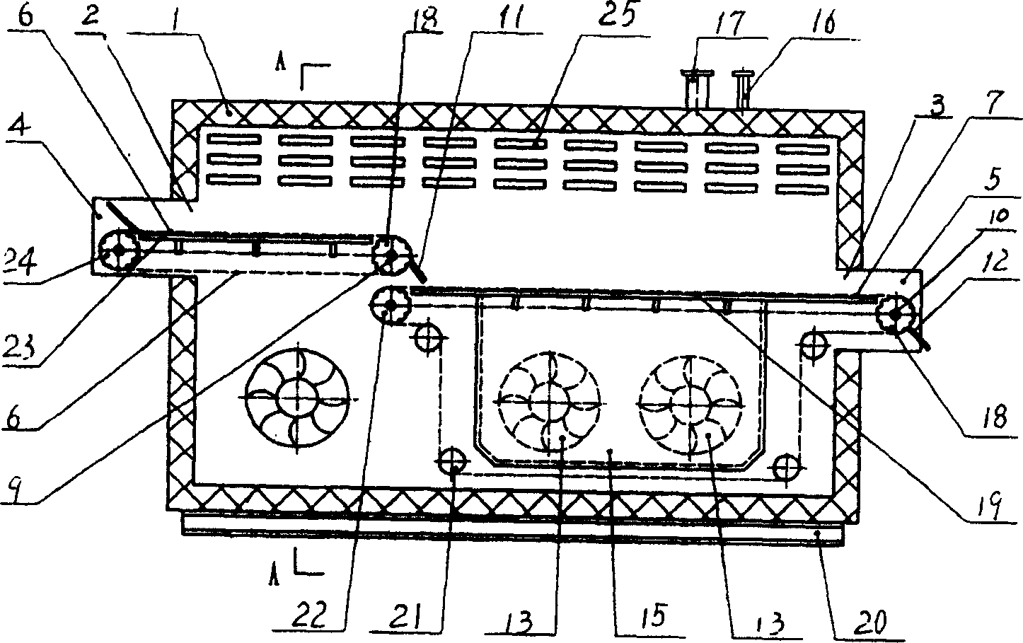
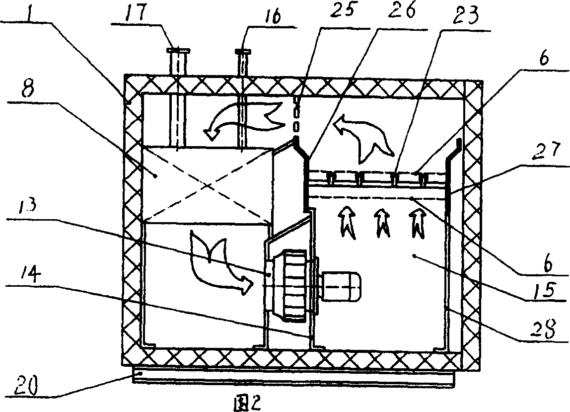
[0026] freezer (see figure 1 ) includes a heat-insulating box body 1, a feed frame 4 and a material-out frame 5 respectively placed in the material inlet 2 and the material outlet 3 of the heat-insulated box body, the first section of circulating conveying mesh belt 6 installed in the heat-insulated box body and the second section The second section of circulating conveying mesh belt 7, the evaporator 8 (seeing Fig. 2 ) positioned at circulating conveying mesh belt 6 and 7 sides, the scraper plates 11 and 12 respectively installed in circulating conveying mesh belt driving wheel shaft 9 and 10 places, respectively The air cooler 13 and the return air passage 25 installed below and above between the evaporator 8 and the circulating conveying mesh belt 6 and 7, the fan frame 14 for the air cooler is connected with the heat-insulating box, and the air outlet of the air cooler is connected with the circulating conveying network The air collection chamber 15 below the belt is conne...

Embodiment 2

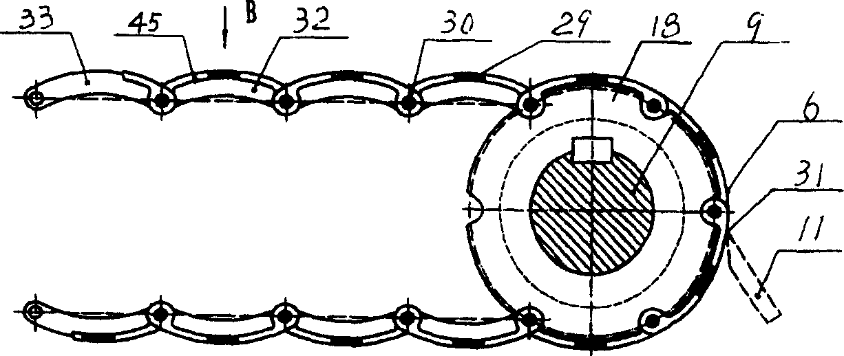
[0028] The difference with Implementation 1 is: in order to meet the needs of the large-load freezing device, the bearing ring and the tension-resistant sheet 36 (see Figure 7 ), the outer circumference radius 39 (see Fig. 8) of the load ring is the same as the outer circumference radius 38 (see Fig. 6) of the pin shaft hole 37 on the convex circular arc working surface shape modular comb member, 30 is movably connected, and the convex arc surface 46 (see Fig. 10 ) of the tensile sheet is lower than the convex arc working surface of the modular comb member 40 on the installed mesh belt. The tooth groove 44 (see FIG. 13 ) of the drive gear 18 corresponds to the position of the anti-tension sheet 36 , and the tooth surface 43 of the drive gear 18 meshes with the bearing ring 35 . In order to increase ventilation and freezing effect, there are ventilation holes 41 and 42 (see Fig. 5 ) on the large-load convex circular arc working surface modular comb-like member 40 (see Fig. 5),...

Embodiment 3

[0030] The difference with embodiment 1 or 2 is: convex circular arc working face shape modular comb member (see image 3 , Fig. 6) is a concave curved surface 45, this structural shape not only reduces the consumption of expensive non-adhesive polytetrafluoroethylene or polyperfluoroethylene propylene, reduces the manufacturing cost, but also helps to reduce the transmission of cold air resistance, improve freezing efficiency.


PUM


Abstract

A refrigeration device comprises an adiabatic box, the corresponding inlet and outlet to the box, two net belts in the box, an evaporator in the box, blower fans, a scraper fixed on the driving shaft of the net belt. The liquid supplier of the evaporator and steam recycle pipe link to the refrigerator. The driving shaft links to an electronic reducer. The first net belt is composed by a teflon arc comb structure and a wrist. The diameter of the arc matches to the diameter of a drive gear installed to the driving shaft.

Description

Technical field: [0001] The invention relates to a freezing device, in particular to a mesh belt type freezing device. Background technique: [0002] In the existing freezing device for conveying frozen products with multi-stage circulating mesh belt, the working surface of the modular comb-shaped member of the conveying mesh belt is a plane. The large plane composed of small planes of the modular comb-shaped member, when the mesh belt runs around the drive gear, the working surface of the mesh belt is folded into a polygonal surface, and the distance between the curved surface and the edge of the scraper will change in size, In addition, the modular plastic comb-shaped member of the existing mesh belt has poor non-adhesiveness. In order to solve the problem of contact between the frozen product containing moisture and the mesh belt that is directly returned to the feeding mechanism and is at freezing temperature For the problem of sticking, the circulating mesh belt often ...

Claims


Application Information

Patent Timeline
Patent Type & Authority Patents(China)
IPC IPC(8): F25D13/06
Inventor 钱洪楼晓华梁惠华
Owner SIFANG TECH GRP CO LTD
Why Eureka
Try Eureka