Combustion chamber base and burner

A technology of combustion chamber and combustion port, which is applied to gas fuel burners, burners, combustion methods, etc. It can solve the problems of changing the heat transfer mode of the burner, not being able to heat the furnace in all directions, and low heat transfer efficiency, and achieves a compact structure , Small space, high heat utilization effect

Active Publication Date: 2018-04-20
SHANDONG QIWEITE SOLAR TECH CO LTD
View PDF10 Cites 0 Cited by
  • Summary
  • Abstract
  • Description
  • Claims
  • Application Information

AI Technical Summary

Problems solved by technology

The combustion chamber of existing liquid heating burners includes boilers, heat-conducting oil furnaces, etc., which usually blow out gas from the bottom to burn, that is, the vertical blowing structure, and its disadvantages are high height, large volume, low heat transfer efficiency, and inability to heat in all directions hearth
This method is also determined by the existing combustion chamber base. It is impossible to fundamentally change the heat transfer mode of the burner without changing the structure of the existing combustion chamber base.

Method used


Image

  • Combustion chamber base and burner
  • Combustion chamber base and burner
  • Combustion chamber base and burner

Examples


Embodiment Construction

[0031] The implementation of the present invention will be illustrated by specific specific examples below, and those skilled in the art can easily understand other advantages and effects of the present invention from the contents disclosed in this specification.

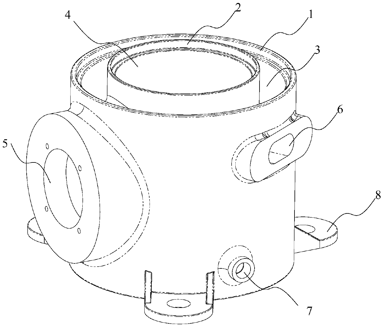
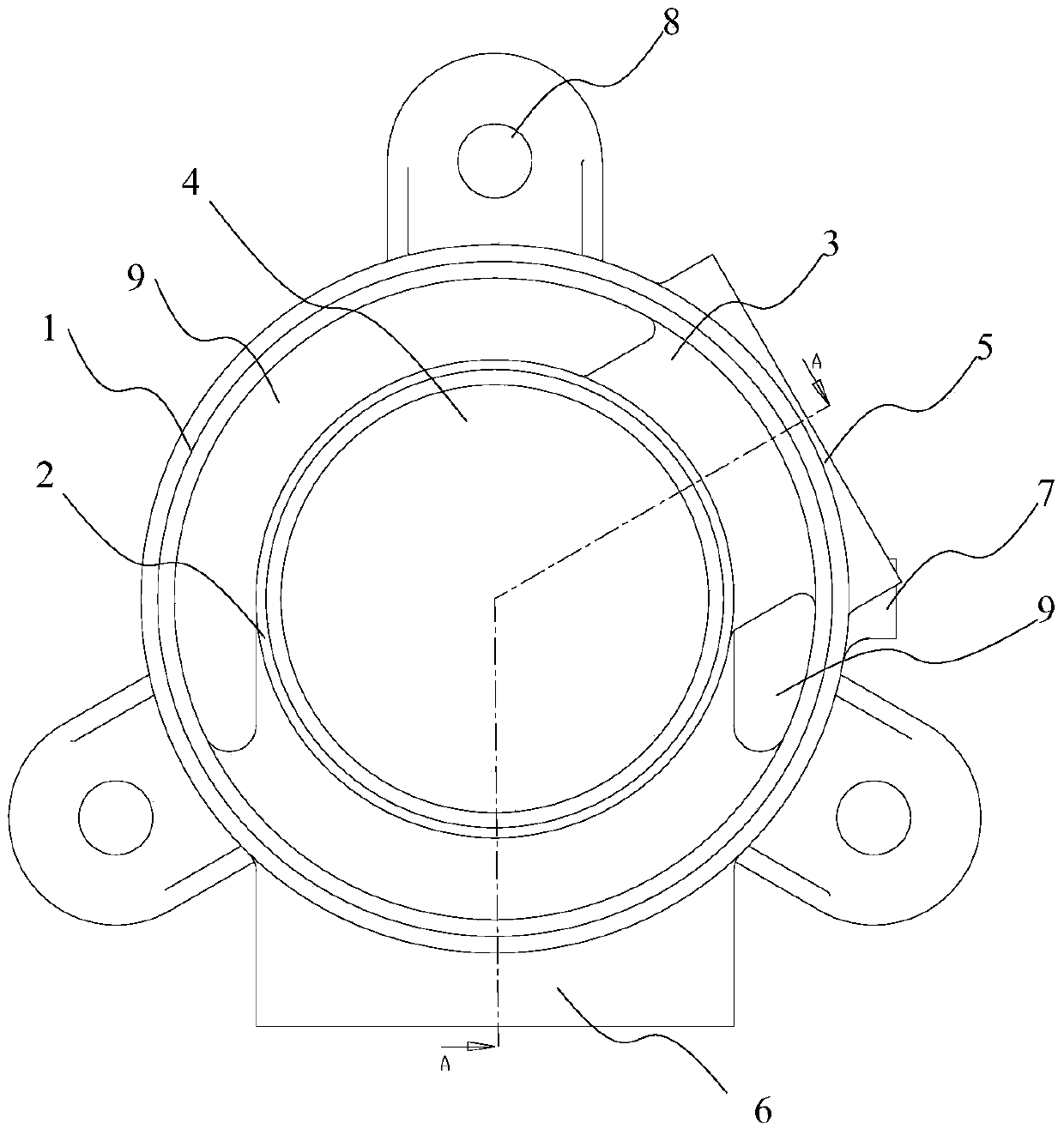
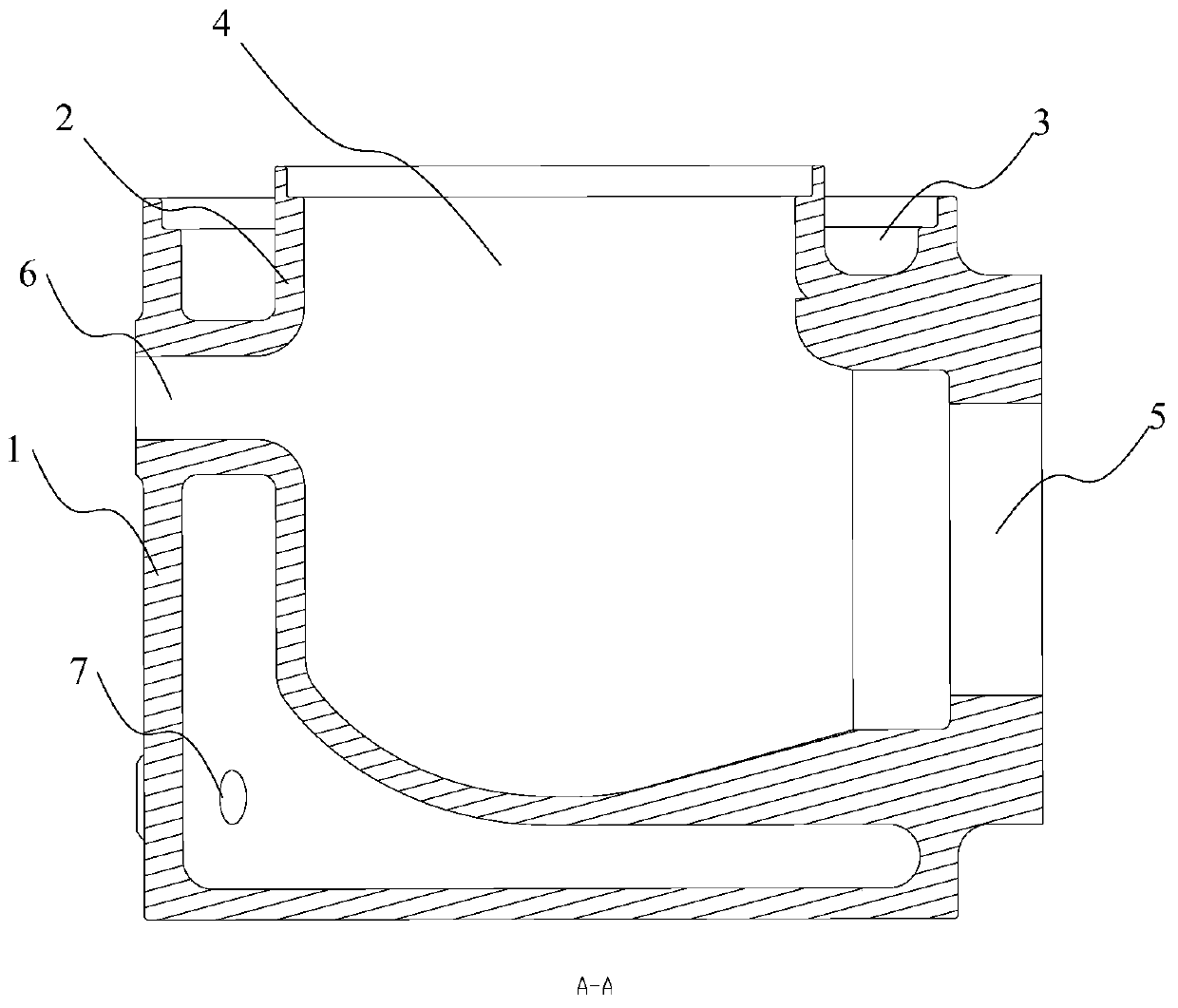
[0032] see Figure 1 to Figure 3 . It should be noted that the structures, proportions, sizes, etc. shown in the drawings attached to this specification are only used to match the content disclosed in the specification, for those who are familiar with this technology to understand and read, and are not used to limit the implementation of the present invention. Limiting conditions, so there is no technical substantive meaning, any modification of structure, change of proportional relationship or adjustment of size, without affecting the effect and purpose of the present invention, should still fall within the scope of the present invention. The disclosed technical content must be within the scope covered. At the sa...


PUM


Abstract

The invention provides a combustion chamber base and a burner, the combustion chamber base includes a first cylinder wall and a second cylinder wall, the second cylinder wall is sleeved in the first cylinder wall; the first cylinder The cavity between the wall and the second cylinder wall forms a solution containing chamber, and the cavity surrounded by the second cylinder wall forms a combustion chamber; and a first combustion port and a second combustion port communicated with the combustion chamber . The burner includes the aforementioned combustion chamber base. The invention realizes that gas is blown into the combustion chamber from the side, and at the same time, the bottom of the furnace is filled with liquid and heated, the bottom heating area is increased compared with the vertical blowing structure, and the heat utilization rate is high. The equipment is simple in structure and easy to process, and is especially suitable for the generator of absorption air conditioning units with compact structure and small space.

Description

technical field [0001] The invention relates to a combustion chamber base and a burner. Background technique [0002] The burner is one of the important components of the direct-fired absorption unit, and its structure plays a vital role in the performance of the unit. The combustion chamber of existing liquid heating burners includes boilers, heat-conducting oil furnaces, etc., which usually blow out gas from the bottom to burn, that is, the vertical blowing structure, and its disadvantages are high height, large volume, low heat transfer efficiency, and inability to heat in all directions hearth. This method is also determined by the existing base of the combustion chamber. It is impossible to fundamentally change the heat transfer mode of the burner without changing the structure of the existing base of the combustion chamber. Contents of the invention [0003] In view of the above-mentioned shortcomings of the prior art, the object of the present invention is to prov...

Claims


Application Information

Patent Timeline
Patent Type & Authority Patents(China)
IPC IPC(8): F23D14/46
Inventor 李文张凤学李振昌边瑞朋马刘红李红玉
Owner SHANDONG QIWEITE SOLAR TECH CO LTD
Why Eureka
Try Eureka