Air source heat pump spray defrosting device based on superhydrophobic finned tube heat exchanger

A technology of finned tube heat exchanger and air source heat pump, which is applied in the operation mode of the machine, the combination of heating and cooling, lighting and heating equipment, etc., can solve the problem that the defrosting efficiency is difficult to improve, the defrosting speed is slow, and the heat consumption is large. And time and other issues, to achieve the effect of not affecting thermal comfort, low heat consumption for defrosting, and improving heating time

Active Publication Date: 2017-10-20
SOUTHEAST UNIV
View PDF5 Cites 1 Cited by
  • Summary
  • Abstract
  • Description
  • Claims
  • Application Information

AI Technical Summary

Problems solved by technology

During the reverse cycle defrosting process, due to the frequent reversing of the four-way valve, the compressor of the refrigeration system will appear "running oil", which will reduce the reliability and service life of the compressor; during defrosting, the refrigerant needs to absorb heat from the heating system. Because of defrosting, the temperature of the heating system fluctuates sharply, which affects the thermal comfort of the heating room
The heat of hot gas bypass defrosting mainly comes from the power consumption of the compressor, the defrosting speed is relatively slow, and it is easy to cause the compressor to absorb liquid during the defrosting process
When the existing defrosting method is used to defrost, the heat pump unit needs to interrupt the heating for defrosting, which makes the heat supply of the unit discontinuous, and the melting of the frost layer on the surface of the evaporator and the evaporation of retained water consume a lot of heat and time during the defrosting process, resulting in It is difficult to improve the defrosting efficiency

Method used


Image

  • Air source heat pump spray defrosting device based on superhydrophobic finned tube heat exchanger

Examples


specific Embodiment approach

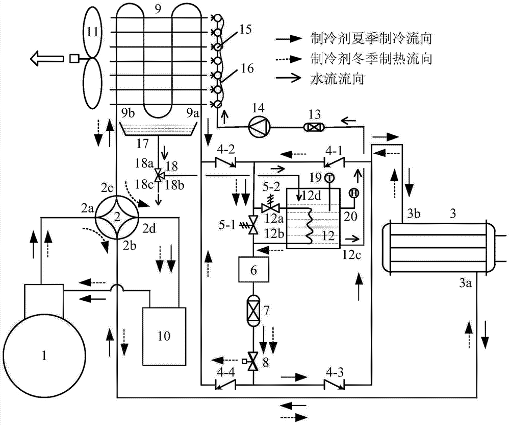
[0028] An air source heat pump spray defrosting device based on a superhydrophobic finned tube heat exchanger includes a refrigerant circuit, a hot water circuit and an air circuit.

[0029] In the refrigerant circuit, the output end of the compressor 1 is connected to the first input end 2a of the four-way valve, the first output end 2b of the four-way valve is connected to the input end 3a of the first heat exchanger, and the output end 3b of the first heat exchanger is divided into Two ways, one way is connected with the inlet of the first one-way valve 4-1, the other way is connected with the outlet of the third one-way valve 4-3, the outlet of the first one-way valve 4-1 is divided into three ways, one way is connected with the second one-way valve The outlet of the one-way valve 4-2 is connected, one way is connected to the input end of the liquid reservoir 6 through the first electromagnetic valve 5-1, and the other way is connected to the first input end 12a of the heat...


PUM


Abstract

An air source heat pump spray defrosting device based on a super-hydrophobic finned tube heat exchanger, comprising a refrigerant loop, a hot water loop, and an air loop. The refrigerant loop comprises a compressor (1), a four-way valve (2), a first heat exchanger (3), a first check valve (4-1), a second check valve (4-2), a third check valve (4-3), a fourth check valve (4-4), a first solenoid valve (5-1), a second solenoid valve (5-2), a liquid reservoir (6), a desiccant filter (7), an electronic expansion valve (8), a finned tube heat exchanger (9), a gas-liquid separator (10), and a heating-type water storage tank (12). The hot water loop comprises the heating-type water storage tank (12), a filter (13), a water pump (14), a nozzle (15), an electric heating tape (16), a water collection pan (17), a three-way valve (18), a temperature sensor (19), and a liquid level sensor (20), wherein a three-way valve first input end (18a), a three-way valve first output end (18b), and a three-way valve second output end (18c) are provided on the three-way valve (18). The air loop comprises the finned tube heat exchanger (9) and a fan (11). Said device spends less time and consume less heat for defrosting, so that continuous heat supply during the defrosting can be realized, and the heat supply time and the heat supply efficiency of the heat pump system are improved.

Description

technical field [0001] The invention belongs to the technical field of design and manufacture of refrigeration and air-conditioning systems, and relates to an air source heat pump spray defrosting method based on a superhydrophobic finned tube heat exchanger and a device for realizing the method. Background technique [0002] Air source heat pumps take into account both refrigeration and heating, and have the advantages of high comprehensive utilization efficiency of primary energy, energy saving, environmental protection, and low initial investment. The vigorous promotion of air source heat pumps is of great significance to improve the comprehensive utilization efficiency of energy in my country and realize energy saving and emission reduction. The biggest problem in the heating operation of air source heat pumps in winter is the frost on the surface of the outdoor fin tube heat exchanger. With the growth of the frost layer between the fins of the heat exchanger, the heat t...

Claims


Application Information

Patent Timeline
Patent Type & Authority Patents(China)
IPC IPC(8): F25B47/00F25B29/00
CPCF25B29/00F25B47/00
Inventor 梁彩华汪峰杨明涛张小松
Owner SOUTHEAST UNIV
Why Eureka
Try Eureka