Fault diagnosis method of cable joint and fault diagnosis device of cable joint

A technology for cable joints and fault diagnosis, applied in the direction of measuring devices, measuring electricity, measuring electrical variables, etc., can solve the problems of accelerated insulation aging at joints, cable fires, and increased probability of partial discharge, avoiding potential safety hazards and low accuracy requirements. , the effect of wide application

Active Publication Date: 2016-02-03
XINJIANG GOLDWIND SCI & TECH
View PDF5 Cites 14 Cited by
  • Summary
  • Abstract
  • Description
  • Claims
  • Application Information

AI Technical Summary

Problems solved by technology

Because the construction quality of the cable joint is not high, and at the same time, abnormal conditions such as vibration and falling will occur during the operation of the wind turbine, resulting in loosening of the cable joint, and then there will be quality problems such as increased contact resistance
What follows is that the operating temperature of the cable joints increases accordingly, thereby accelerating the aging of the insulation at the joints, increasing the probability of partial discharge and forming a vicious circle, which eventually leads to high temperature failures and cable fires
[0004] The power cable is a multi-core cable joint, therefore, the existing method is not suitable for the fault diagnosis of the power cable, nor can it avoid the potential safety hazards caused by the failure of the cable joint
In addition, the existing technology usually directly uses the temperature measurement results as the basis for fault judgment. Therefore, in order to improve the accuracy of fault judgment, it is necessary to use a high-precision temperature measurement device, which in turn leads to high fault diagnosis costs.

Method used


Image

  • Fault diagnosis method of cable joint and fault diagnosis device of cable joint
  • Fault diagnosis method of cable joint and fault diagnosis device of cable joint
  • Fault diagnosis method of cable joint and fault diagnosis device of cable joint

Examples


Embodiment 1

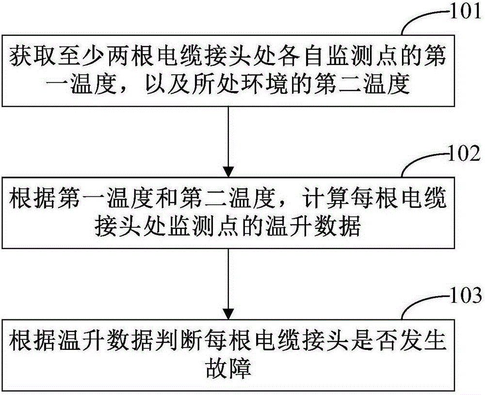
[0021] figure 1 It is a schematic flow chart of a fault diagnosis method for a cable joint according to Embodiment 1 of the present invention, as figure 1 As shown, the fault diagnosis methods for cable joints include:

[0022] Step 101: Obtain first temperatures of respective monitoring points at at least two cable joints, and second temperatures of environments where at least two cable joints are located.

[0023] In practical applications, the location of the monitoring point can be determined according to the actual conditions on site and the reliability of the equipment. Generally, the insulation sheath at the cable joint is selected as the location of the monitoring point. Correspondingly, the first temperature may be the temperature of a certain monitoring point on the insulation sheath of each cable joint, which may be collected by a temperature measuring sensor and / or an infrared temperature measuring device to obtain the first temperature of each monitoring point at...

Embodiment 2

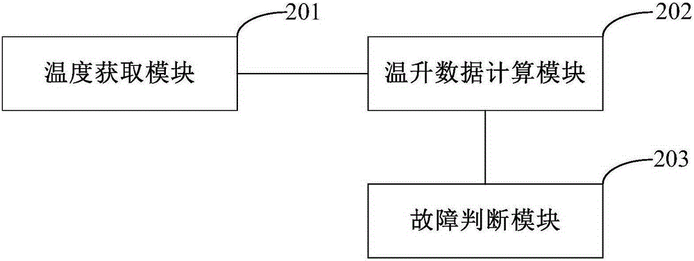
[0045] figure 2 It is a schematic structural diagram of a fault diagnosis device for a cable joint according to Embodiment 2 of the present invention. It can be used to execute the steps of the fault diagnosis method for the cable joint in Embodiment 1 of the present invention.

[0046] refer to figure 2 , the cable joint fault diagnosis device includes a temperature acquisition module 201 , a temperature rise data calculation module 202 and a fault judgment module 203 .

[0047] The temperature obtaining module 201 is used to obtain the first temperature of each monitoring point at the at least two cable joints, and the second temperature of the environment where the at least two cable joints are located.

[0048] Preferably, the temperature acquisition module 201 includes a temperature measurement sensor and / or an infrared temperature measurement device.

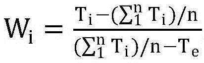
[0049] The temperature rise data calculation module 202 is used to calculate the temperature rise data of the monit...


PUM


Abstract

The embodiment of the present invention provides a fault diagnosis method of a cable joint and a fault diagnosis device of a cable joint. The fault diagnosis method of the cable joint comprises: obtaining a first temperature of each monitoring point at the joints of at least two cables and a second temperature of an environment at the joints of the at least two cables; calculating temperature rise data of each monitoring point at the joints of the cables with respect to the environment according to the obtained first temperature and second temperature; and determining whether the cable joints have faults or not according to the temperature rise data. According to the fault diagnosis method of the cable joint and the fault diagnosis device of the cable joint, fault monitoring of the cable joint may be realized, potential risk caused by the faults of the cable joint may be avoided, and the precision requirement of a temperature sensor is low so that the cost is reduced.

Description

technical field [0001] The invention relates to the technical field of cable fault monitoring, in particular to a fault diagnosis method and device for a cable joint. Background technique [0002] In large-scale power supply systems, more and more power cables are used for power transmission and distribution. Faults caused by power cables are the main factor affecting the normal supply of electricity. However, cable operation failures mostly occur at the cable joints. Generally, the existing fault diagnosis methods for cable joints are mainly suitable for high-voltage power systems, and are not suitable for fault monitoring of multi-core cable joints. [0003] Take the power cables used in the wind power field as an example. Due to the high height of the generator, the construction is more difficult, and the power cables are generally connected by cable joints. Because the construction quality of the cable joint is not high, and abnormal conditions such as vibration and ...

Claims


Application Information

Patent Timeline
Patent Type & Authority Applications(China)
IPC IPC(8): G01R31/02G01R31/12
Inventor 马彬锐
Owner XINJIANG GOLDWIND SCI & TECH
Why Eureka
Try Eureka