uv LED light source structure and parallel light exposure machine

A technology of parallel light lens and light source, which is applied in the field of exposure machines, can solve the problems of delay in production, complex structure, high cost, etc., and achieve the effect of high power consumption, simple optical structure, and avoid delay in production

Active Publication Date: 2017-10-10
张河生
View PDF5 Cites 1 Cited by
  • Summary
  • Abstract
  • Description
  • Claims
  • Application Information

AI Technical Summary

Problems solved by technology

[0010] The purpose of the present invention is to provide a UV LED light source structure, aiming to solve the problem that the parallel light exposure machine in the prior art adopts UV LED light source and needs to redesign the optical structure, resulting in high cost, complicated structure and delayed production

Method used


Image

  • uv LED light source structure and parallel light exposure machine
  • uv LED light source structure and parallel light exposure machine
  • uv LED light source structure and parallel light exposure machine

Examples


Embodiment Construction

[0022] In order to make the object, technical solution and advantages of the present invention clearer, the present invention will be further described in detail below in conjunction with the accompanying drawings and embodiments. It should be understood that the specific embodiments described here are only used to explain the present invention, not to limit the present invention.

[0023] The implementation of the present invention will be described in detail below in conjunction with specific embodiments.

[0024] refer to Figure 2-7 Shown is the preferred embodiment provided by the present invention.

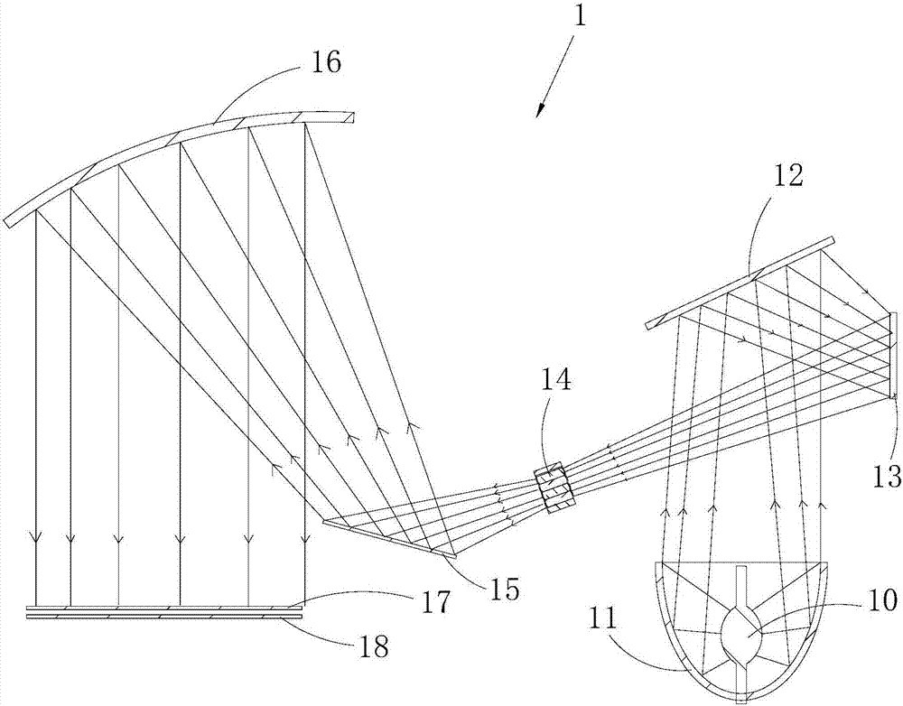
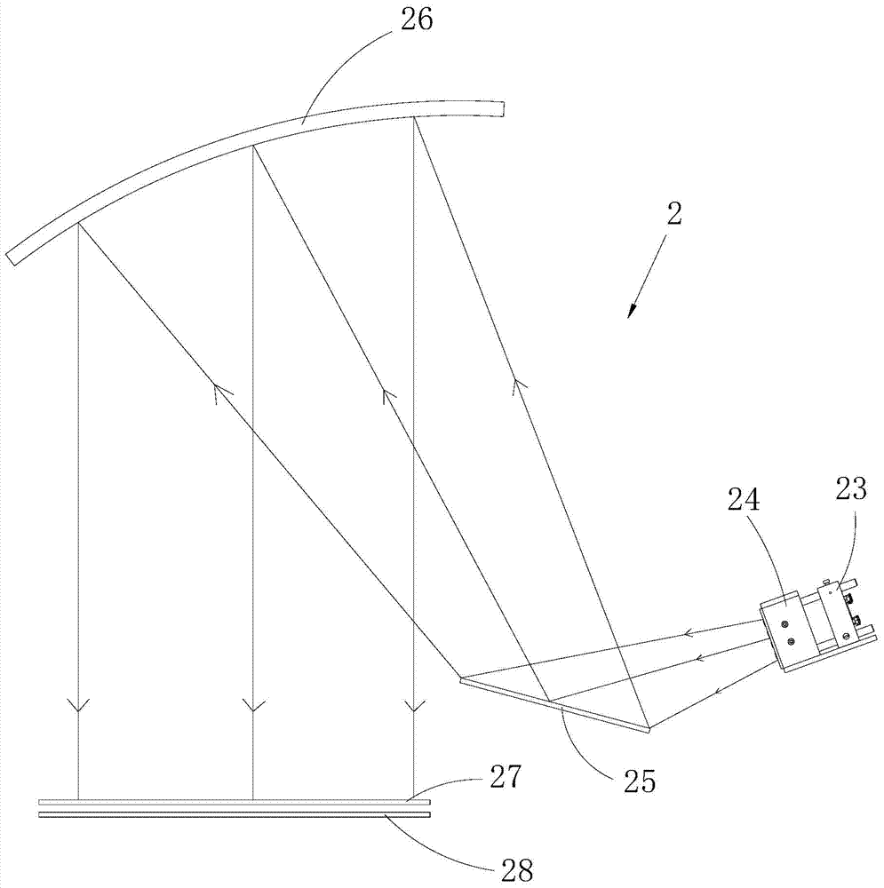
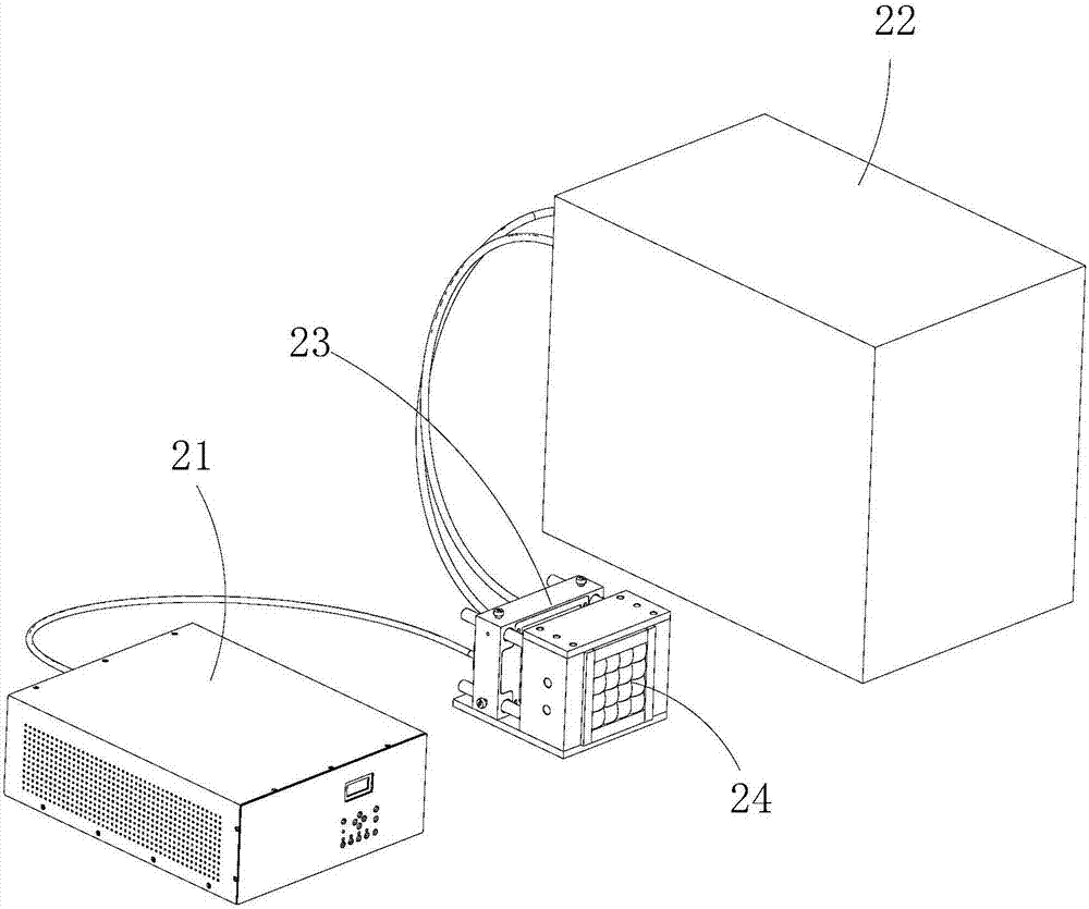
[0025] As shown in references 2 to 5, the UV LED light source structure 2 provided by the present invention is used in a parallel light exposure machine, or it can also be used in other equipment that requires exposure, and is not limited to the parallel light exposure in this embodiment machine.

[0026] The UV LED light source structure 2 includes a UV LED lamp holder 2...


PUM

PropertyMeasurementUnit
hardnessaaaaaaaaaa
hardnessaaaaaaaaaa

Abstract

The invention relates to the technical field of exposure machines, and discloses a UV LED light source structure and a parallel light exposure machine, including a UV LED lamp head, a fly-eye lens module, a plane mirror and a spherical mirror, along the light path direction of the UV LED light source structure, a UV LED lamp head, and a fly-eye lens. The module, plane mirror and spherical mirror are arranged in sequence; UV LED lamp beads are arranged in the UV LED, and the UV LED lamp head and the fly-eye lens module are arranged in parallel adjacent to each other. The distance adjustment mechanism is connected. The UV LED lamp head is placed in front of the fly-eye lens module, and the parallel light for exposure is formed by using the fly-eye lens module, plane mirror and spherical mirror; the UV LED light source structure is used in the existing parallel light exposure machine without the need for customers Renewing equipment does not require large-scale modification of equipment, and at the least cost, you can obtain a low-temperature, energy-saving, environmentally friendly, and safe exposure machine with UV LED light source structure, avoiding delays in production, and greatly reducing costs.

Description

technical field [0001] The invention relates to the technical field of exposure machines, in particular to a UV LED light source structure and a parallel light exposure machine including the UV LED light source structure. Background technique [0002] refer to figure 1 Shown is the light source structure 1 of a traditional parallel light exposure machine. The traditional parallel light exposure machine uses an ultra-high pressure mercury lamp 10 as a light source. The ultra-high pressure mercury lamp 10 first collects light through an elliptical mirror 11, and the light converges to On a first plane mirror 12, the first plane mirror 12 transmits the high-calorie IR light (infrared light) part in the light of the ultra-high pressure mercury lamp 10, and reflects and converges the UV light (ultraviolet light) in the ultra-high pressure mercury lamp 10 to On the second plane mirror 13, the second plane mirror 13 further reflects and converges the UV light almost without loss t...

Claims


Application Information

Patent Timeline
Patent Type & Authority Patents(China)
IPC IPC(8): G03F7/20
Inventor 张河生唐威张春玲
Owner 张河生
Why Eureka
Try Eureka