Shifting register, shifting register circuit and display device

A shift register and shift register technology, applied in static memory, digital memory information, instruments, etc., can solve problems affecting circuit stability, etc., and achieve the effects of poor stability, excellent transmission performance, and stable work

Active Publication Date: 2016-02-03
WUHAN TIANMA MICRO ELECTRONICS CO LTD +1
View PDF4 Cites 20 Cited by
  • Summary
  • Abstract
  • Description
  • Claims
  • Application Information

AI Technical Summary

Problems solved by technology

[0004] It can be seen that the shift register provided by the prior art has the risk of competition, which affects the stability of the circuit.

Method used


Image

  • Shifting register, shifting register circuit and display device
  • Shifting register, shifting register circuit and display device
  • Shifting register, shifting register circuit and display device

Examples


Embodiment Construction

[0028] In order to make the purpose, technical solutions and advantages of the present invention clearer, the technical solutions of the present invention will be clearly and completely described through implementation with reference to the accompanying drawings in the embodiments of the present invention. Obviously, the described embodiments are the embodiment of the present invention. Some, but not all, embodiments. Based on the embodiments of the present invention, all other embodiments obtained by persons of ordinary skill in the art without making creative efforts belong to the protection scope of the present invention.

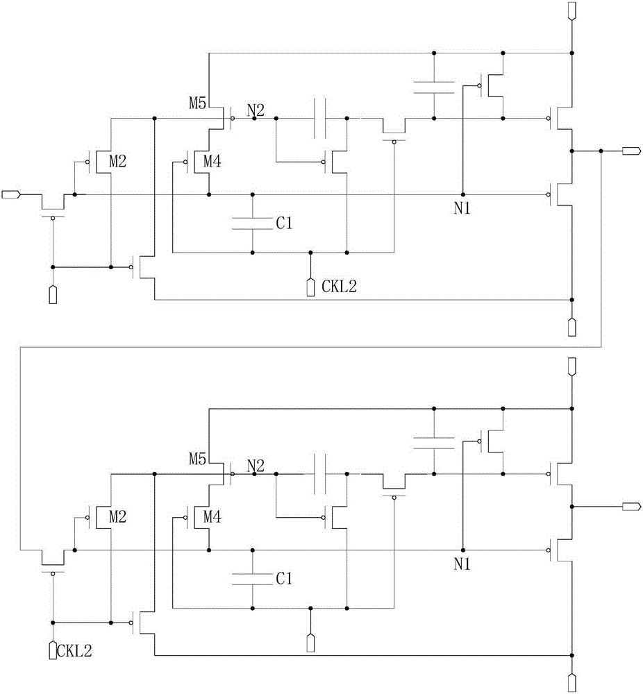
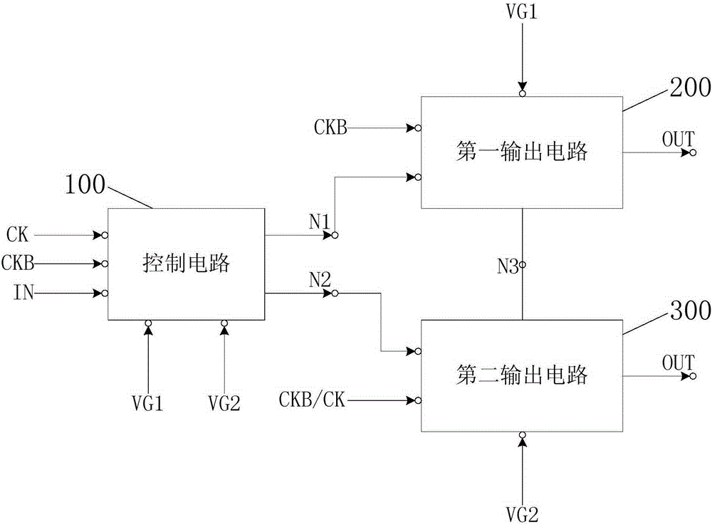
[0029] refer to figure 2 As shown, it is a schematic diagram of a shift register provided by an embodiment of the present invention. The technical solution of this embodiment is applicable to the situation of improving the stability of the shift register. As shown in the figure, the shift register includes: a control circuit 100 , a first output circu...


PUM


Abstract

The invention discloses a shifting register, a shifting register circuit and a display device. The shifting register comprises a control circuit, a first output circuit and a second output circuit. The control circuit is used for controlling potential of a first control node and a second control node; a signal input end of the first output circuit is connected with a shifting register signal output end under the control of the control circuit, so that first level signals transmitted by a first level signal end can be outputted; or a signal input end of the second output circuit is connected with the shifting register signal output end under the control of the control circuit, so that second level signals transmitted by a second level signal end can be outputted. The shifting register, the shifting register circuit and the display device have the advantages that the shifting register is good in stability and excellent in transmission performance and performance and can work stably, and problems of poor stability and instable work of a shifting register in the prior art can be solved.

Description

technical field [0001] The invention relates to display technology, in particular to a shift register, a shift register circuit and a display device. Background technique [0002] The shift register is used to register data, and is also used to shift the data in it to the left or right in sequence under the action of the clock signal. [0003] For example, the patent solution provided by the patent number US20140055444A1, its shift register is as follows Figure 1a As shown, its circuit timing diagram is shown in Figure 1b As shown, it is divided into the timing of t1 ~ t6, and the timing after t6. combine Figure 1a and Figure 1b As shown, the shift register will have the following two situations at time t5: 1. Since CLK2 becomes low, CLK2 will pull down the N1 node through the coupling of C1, M2 will be turned on, and N2 will be set high, and the shift register 2. Because CLK2 becomes low, CLK2 will pull down the N1 node through the coupling of C1, but because N2 is l...

Claims


Application Information

Patent Timeline
Patent Type & Authority Applications(China)
IPC IPC(8): G09G3/32G11C19/00
Inventor 李元钱栋
Owner WUHAN TIANMA MICRO ELECTRONICS CO LTD
Why Eureka
Try Eureka