Pulse transformer

A technology of pulse transformers and magnetic cores, applied in the field of transformers, can solve problems such as low-voltage circuits and device damage

Active Publication Date: 2016-02-03
深圳市普扬技术有限公司
View PDF5 Cites 3 Cited by
  • Summary
  • Abstract
  • Description
  • Claims
  • Application Information

AI Technical Summary

Problems solved by technology

[0004] The purpose of the present invention is to provide a vehicle-mounted overvoltage protection circuit, aiming to solve the problem

Method used


Image

  • Pulse transformer
  • Pulse transformer
  • Pulse transformer

Examples


Embodiment approach

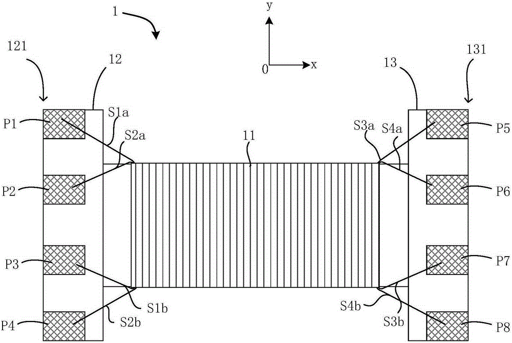
[0034] The first kind, refer to figure 2 and Figure 5 , the first electrode P1, the second electrode P2, the third electrode P3, and the fourth electrode P4 are equidistantly arranged, and the fifth electrode P5, the sixth electrode P6, the seventh electrode P7, and the eighth electrode P8 are equidistant Arrange settings.

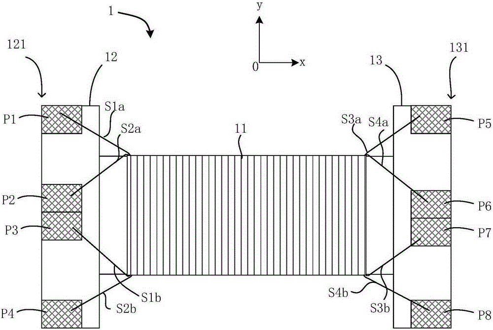
[0035] The second, refer to image 3 and Image 6 , the second electrode P2 and the third electrode P3 are arranged close to the middle of the side 121 of the first boss 12, so that the second electrode P2 and the third electrode P3 are respectively far away from the first electrode P1 and the fourth electrode P1. The electrode P4; the sixth electrode P6 and the seventh electrode P7 are arranged close to the middle part 131 of the side of the second boss 13, so that the sixth electrode P6 and the seventh electrode P7 are respectively far away from the fifth electrode P5, The eighth electrode P8.

[0036] In the third type, refer to Figure 4 and ...


PUM


Abstract

The invention provides a pulse transformer, comprising a magnetic core composed of a first magnetic core body and a second magnetic core body, wherein winding wires are wound on the first magnetic core body in advance to form a corresponding winding coil, and then the first magnetic core body is mounted on the second magnetic core body so that the first magnetic core body and the second magnetic core body form a closed magnetic circuit, the winding coil comprises a first winding and a second winding, the first winding comprises two first winding wires, the first ends of the two first winding wires are respectively connected with a first electrode and a second electrode, the second ends of the two first winding wires are respectively connected with a third electrode and a fourth electrode, the second winding comprises two second winding wires, the first ends of the two second winding wires are respectively connected with fifth and sixth electrodes, the second ends of the two second winding wires are respectively connected with seventh and eighth electrodes. The start and tail ends of the two windings are both arranged on the same side of the first magnetic core body, and thus the insulation capability of primary and secondary windings can be improved and the requirement on magnetic core material can be reduced further.

Description

technical field [0001] The invention relates to transformer technology, in particular to a pulse transformer. Background technique [0002] In recent years, pulse transformers that insulate differential signals on the input side and differential signals on the output side have been widely used in circuit components such as connectors. In traditional pulse transformers, in order to achieve a higher magnetic coupling effect, reduce magnetic flux leakage, and improve communication bandwidth, a magnetic ring is usually used as the core body. The magnetic ring structure can achieve a higher signal bandwidth, but the magnetic ring structure Belonging to the closed structure, it is not conducive to realizing the automatic winding process, especially for the magnetic core with a small inner hole of the magnetic ring. At present, a large number of manual threading is used in the industry, which not only has low production efficiency, but also has uneven product quality and large dev...

Claims


Application Information

Patent Timeline
IPC IPC(8): H01F19/08H01F27/29H01F27/28H01F27/30H01F27/24
Inventor 吴林熙
Owner 深圳市普扬技术有限公司
Why Eureka
Try Eureka