
Radar antenna lifting mechanism design

A technology of lifting mechanism and radar antenna, applied in the direction of antenna support/installation device, etc., can solve the problems of inconvenient maintenance, poor processing technology, low crossing rate, etc., achieve easy processing, installation and maintenance, reasonable structural design, and improve maintenance performance effect

Inactive Publication Date: 2016-02-03
WUHU HANGFEI SCI & TECH
View PDF0 Cites 3 Cited by
  • Summary
  • Abstract
  • Description
  • Claims
  • Application Information

AI Technical Summary

Problems solved by technology

This structure has a variety of adverse effects. First, it is heavy, and many indicators of the antenna base, such as motor power, reducer, natural frequency and overall structure, are unfavorable. Second, the complex structure and precision debugging increase the workload of the installation site. And it is not easy to maintain. Third, its processing technology is poor and the cost is high.
However, the existing large-scale antenna bases mostly use straight tooth transmission or screw transmission. The former makes the structure huge, while the latter has low crossing rate and slow speed.
In addition, when the existing antenna base is being maintained, it is sometimes necessary to remove the antenna, which reduces the maintainability index of the system

Method used


Image

  • Radar antenna lifting mechanism design
  • Radar antenna lifting mechanism design

Examples


Embodiment Construction

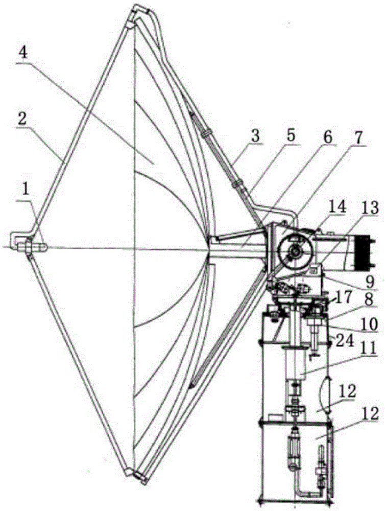
[0011] refer to Figure 1 to Figure 2 , the lifting mechanism 24 of the present invention is fixed on the outer sides of the azimuth casing 8 with fasteners, and its effect is that the azimuth gears such as the azimuth transmission 13 and the azimuth shaft 17 in the azimuth casing 8 need to be maintained. The mechanism separates the pitch box 9 from the azimuth box 8, and utilizes the gap raised by the azimuth box 9 to remove the azimuth bearing or to repair the azimuth transmission mechanism. Maintenance and replacement can be carried out without dismantling the antenna, which facilitates the maintenance of the antenna and reduces the maintenance workload. Lifting mechanism 24 is made up of fixed mechanism 18, leading screw 19, slide block 20, both sides cushion block 21, center cushion block 22, swing mechanism 23. Fixing mechanism 18 is fixedly installed on the both sides of azimuth casing 8 with fastener, swing mechanism 23 is connected with lifting mechanism 7 with faste...


PUM


Abstract

The invention discloses a radar antenna lifting mechanism design, which relates to a communication antenna in the meteorological communication field. The radar antenna lifting mechanism design is composed of a fixing mechanism, a screw rod, a sliding block, a two-side cushion block, a central cushion block, and a swinging mechanism, wherein the fixing mechanism is fixed on two outer side surfaces of an azimuth box by using fasteners; the screw rod is movably arranged on the fixing mechanism; the sliding block and the screw rod are in threaded connection and then arranged on the fixing mechanism; the two-side cushion block is movably arranged inside the fixing mechanism on the sliding block; the swinging mechanism is movably arranged on the fixing mechanism by using a bolt; the central cushion block is movably fixed on the fixing mechanism by using a bolt; and the upper end surface of the swinging mechanism is detachably arranged and connected with the lifting mechanism. The invention provides an antenna servo device which is simple in structure, convenient to mount and maintain and high in precision. The mechanism of the invention also has advantages of good mechanical structure technological performance, light weight, low cost, good electrical performance and the like, and is particularly suitable for serving as a weather early warning radar antenna servo device.

Description

technical field [0001] The invention relates to a radar antenna in the field of meteorological communication, and is especially suitable for a lifting mechanism of a weather early warning radar antenna. Background technique [0002] At present, the large-aperture antenna structure generally adopts a relatively complex steel material back frame structure, and at the same time, the accuracy of the reflective surface, an important index of the antenna structure, needs to be debugged at the installation site. This structure has a variety of adverse effects. First, it is heavy, and many indicators of the antenna base, such as motor power, reducer, natural frequency and overall structure, are unfavorable. Second, the complex structure and precision debugging increase the workload of the installation site. And it is not easy to maintain, and the 3rd, its processability is poor, and cost is high. However, most of the existing large-scale antenna bases adopt straight-tooth transmiss...

Claims


Application Information

Patent Timeline
IPC IPC(8): H01Q1/12
Inventor 宋琪陈之典罗诗旭王宇航檀剑飞汪言康陈坤朱倩邓禹
Owner WUHU HANGFEI SCI & TECH
Learn More