
A combined antenna and an electronic device

A technology of combining antennas and antennas, which is applied in the electronic field, can solve the problems of large area of ​​printed circuit boards, etc., and achieve the effect of solving the problem of excessive area

Active Publication Date: 2019-02-05
LENOVO (BEIJING) LTD
View PDF5 Cites 0 Cited by
  • Summary
  • Abstract
  • Description
  • Claims
  • Application Information

AI Technical Summary

Problems solved by technology

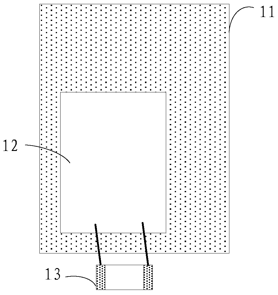
[0006] The present invention provides a combination antenna and an electronic device, which are used to solve the technical problem that the reference ground part of the electromagnetic radiation antenna in the prior art causes the area of ​​the printed circuit board to be too large

Method used


Image

  • A combined antenna and an electronic device
  • A combined antenna and an electronic device
  • A combined antenna and an electronic device

Examples


Embodiment 1

[0055] An embodiment of the present invention provides a combined antenna, such as figure 2 As shown, the combined antenna includes: a first antenna of the electromagnetic induction type, and a second antenna of the electromagnetic radiation type;

[0056] The first antenna includes a conductive substrate 21;

[0057] The main part 22 of the second antenna is connected to the substrate 21 of the first antenna, and the substrate is used as a reference ground part of the second antenna.

[0058] in addition, figure 2 Also shows the antenna coil 23 of the first antenna, the antenna coil 23 of the first antenna is located on the surface of the substrate 21, in the specific implementation process, in order to avoid the electromagnetic field generated by the first antenna The impact of the conductive substrate 21 produces a vortex effect, and it is usually necessary to set up a layer of ferrite film between the antenna coil 23 of the first antenna and the substrate 21, such as i...

Embodiment 2

[0078] An embodiment of the present invention provides an electronic device, such as Figure 8 As shown, the electronic equipment includes:

[0079] housing 81;

[0080] Antenna module 82, arranged in the housing 81;

[0081] The antenna module includes a combination antenna, and the combination antenna includes a first antenna of the electromagnetic induction type, and a second antenna of the electromagnetic radiation type;

[0082] The first antenna includes a conductive substrate;

[0083] The main part of the second antenna is connected to the substrate of the first antenna, and the substrate is used as a reference ground part of the second antenna.

[0084] It should be noted that, for the specific implementation manner of the combined antenna, reference may be made to the corresponding content in the first embodiment above, and for the sake of brevity of description, details are not repeated here.

[0085] Optionally, as in Figure 8 As shown, the electronic device ...


PUM


Abstract

Embodiments of this application provide a combine antenna and an electronic device. The combined antenna includes a first antenna of an electromagnetic induction type and a second antenna of an electromagnetic radiation type. The first antenna includes a substrate having an electrical conductivity with a body portion of the second antenna connected to the substrate of the first antenna, the substrate serving as a reference ground portion of the second antenna.

Description

technical field [0001] The present application relates to the field of electronic technology, in particular to a combined antenna and an electronic device. Background technique [0002] With the rapid development of electronic technology, existing electronic devices can often use a variety of antennas to receive different signals, such as Bluetooth antennas, near field communication (English full name: Near Field Communication, NFC for short) antennas, wireless charging Antenna etc. [0003] Among them, the NFC antenna and the wireless charging antenna belong to the application of electromagnetic induction, and the Bluetooth antenna belongs to the application of electromagnetic radiation. Among them, the antenna of the electromagnetic induction type does not need a reference ground part, while the antenna of the electromagnetic radiation type needs a reference ground part. [0004] In the prior art, in order to reduce the size of the electromagnetic radiation antenna, the r...

Claims


Application Information

Patent Timeline
Patent Type & Authority Patents(China)
IPC IPC(8): H01Q1/48H01Q21/00H01Q1/22
CPCH01Q21/30H01Q1/243H01Q1/38H01Q1/48H01Q7/06
Inventor 沈建靓崔斌
Owner LENOVO (BEIJING) LTD
Learn More