Wire connector

A wire splicer and splicer technology, applied in the direction of adjusting/maintaining mechanical tension, cable suspension devices, etc., can solve the problems of poor mechanical bearing capacity, wire falling off, and cumbersome pressing tools, etc. The effect of stable and reliable use and good tension bearing capacity

Active Publication Date: 2016-02-03
GUANGZHOU PANYU CABLE WORKS
View PDF9 Cites 2 Cited by
  • Summary
  • Abstract
  • Description
  • Claims
  • Application Information

AI Technical Summary

Problems solved by technology

[0005] ① Construction personnel must use professional compression tools such as hydraulic pliers when working in the air, and professional compression tools such as hydraulic pliers are heavy and inconvenient to carry;
[0006] ②The operation of connecting wires is complicated, and the construction safety is insufficient, which is not conducive to shortening the time of aerial work, resulting in increased operating risks for construction personnel;
[0007] ③ It is a one-time product. After being installed on the wire, it cannot be disassembled, which is inconvenient for post-processing operation, cannot be reused, and has high cost;
[0008] ④ For the mechanical strength of the connection point, only one connection tube and 3 repair tubes are allowed on each conductor (lightning conductor) within one span. sex is relatively poor
[0010] ①Use the locking bolts to lock the two clamps to fasten the wires. The overhead wires are exposed to the outdoors and are easily affected by the environment and cause the locking bolts to loosen. Once the locking bolts are loose, the connected wires will easily fall from the clamp Falling off, affecting the reliability and safety of wire connection;
[0011] ② The mechanical strength and mechanical bearing capacity of the connection point are poor, and it is only suitable for parts that do not bear tension, and the applicability is poor;
[0012] ③The reliability of wire connection is poor, regular inspection and maintenance are required, and the cost is high

Method used


Image

  • Wire connector
  • Wire connector
  • Wire connector

Examples


Embodiment 1

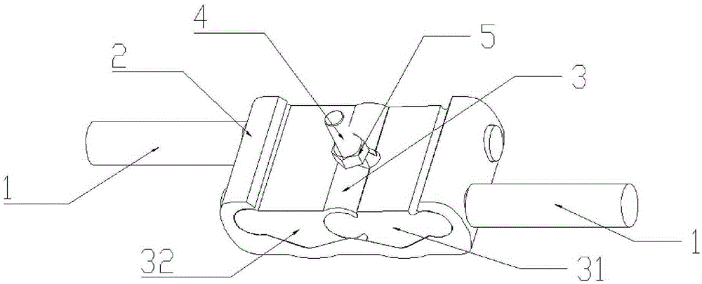
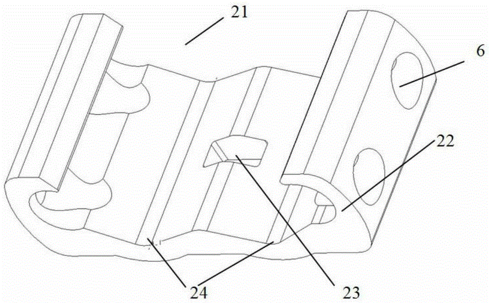
[0063] A wire connector includes a connector body 2, a locking block 3 on the connector body 2, and a locking device for detachably connecting the connector body 2 and the locking block 3. One surface of the connector body 2 Correspondingly, a concave-convex crimping structure is provided on one surface of the locking block 3, and at least one of the connector body 2 and the locking block 3 is provided to prevent The limiting structure for the wire to slide down laterally. When in use, the wire is set between the concave and convex crimping structure of the connector body 2 and the concave and convex crimping structure of the locking block 3, and is limited by the limiting structure. Under the action of the tightening force, the wire is locked and bent to prevent longitudinal sliding.

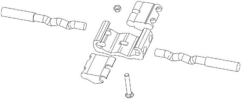
[0064] The wire connector is provided with at least two connector bodies 2, and each connector body 2 is provided with a locking block 3 and a locking device for detachably connecting the connecto...

Embodiment 2

[0075] On the basis of the technical solution of the wire terminal clamp described in Embodiment 1, the following improvements are further made:

[0076] Such as image 3 As shown, the main body groove is a "C-shaped" groove, or the main body groove is an "O-shaped" groove. The locking device includes a locking screw 4.

[0077] The body groove is a "C-shaped" groove, and the connector body 2 and the locking block 3 are respectively provided with a first hole and a second through hole, and the second through hole is located in one of the sub-blocks. On or between the two sub-blocks, the first through hole and the second through hole are both light holes, and the locking screw 4 passes through the first through hole and the second through hole to cooperate with a locking nut 5, The connector body 2 and the locking block 3 can be detachably connected and locked, or one of the first through hole and the second through hole is a light hole, and one through hole can be connected to the...

Embodiment 3

[0085] On the basis of the technical solution of the wire terminal clamp described in Embodiment 1 or Embodiment 2, the following improvements are further made:

[0086] The locking screw 4 is arranged at the center of the terminal clamp body 2, and the installation direction of the locking screw 4 is perpendicular to the wire insertion direction.

[0087] Such as Figure 1 to 7 As shown, the locking block 3 is composed of two sub-blocks, a male block 31 and a female block 32, the opposite ends of the male block 31 are convex arc structures, and one end of the female block 32 is a convex arc The opposite end of the convex arc structure and the concave arc structure are both greater than 180°. The convex arc structure at one end of the male block 31 is hinged to the connector body 2, and the other end The convex arc structure of the female block 32 is fitted into the concave arc structure of the female block 32 to form an articulation. The convex arc structure of the female block 3...


PUM


Abstract

The invention discloses a wire connector. The wire connector comprises connector bodies, locking blocks arranged on the connector bodies, and locking devices for detachable connection with the connector bodies and the locking blocks. One surface of each connector body is provided with a concave-convex pressing line structure, correspondingly, one surface of each locking block is provided with a matched concave-convex pressing line structure, and at least one from each connector body and each locking block is provided with a limiting structure for preventing wires from transversely slipping off. The wire connector provided by the invention has the advantages of simple structure, good wire clamping effect, excellent tension bearing capability, good electrical property, convenient connection installation, flexible dismounting, high versatility, capability of self-locking, convenient unlocking and safe and stable connection.

Description

Technical field [0001] The invention belongs to the field of wire connection, and relates to a load-bearing connection fitting: a wire connector. Background technique [0002] In the process of power transmission, the conductive connection of the wire is divided into two situations, the shunt of the wire and the connection of the wire; the connection device used for the shunt of the wire is generally a non-load-bearing fitting, as disclosed in the Chinese patent with the patent number ZL201420359040.0 The fittings named "a kind of electric meter wiring clamp", the Chinese patent publication with the patent number ZL201020103747.7, the fittings named "reinforced C-type clamp", the Chinese patent publication with the patent number 201210577375.5 is named "a Parallel connection cable clamps, etc. These non-load-bearing fittings are not suitable for connecting wires due to insufficient mechanical strength of the wire connection points, which are easy to destroy themselves or separate...

Claims


Application Information

Patent Timeline
Patent Type & Authority Applications(China)
IPC IPC(8): H02G7/02H02G7/05
Inventor 胡超强尤占山安向阳覃丹王利江卢广业张仕欢申常伟陈雪儿何平
Owner GUANGZHOU PANYU CABLE WORKS
Why Eureka
Try Eureka