Long-distance wireless transmission device with controllable transmission range

A technology of wireless power transmission and power transmission device, applied in the direction of electromagnetic wave system, etc., can solve the problems of limited application range, reduced transmission efficiency, energy loss, etc.

Inactive Publication Date: 2016-02-03
SHANGHAI JIAO TONG UNIV
View PDF4 Cites 2 Cited by
  • Summary
  • Abstract
  • Description
  • Claims
  • Application Information

AI Technical Summary

Problems solved by technology

However, each step in this process may cause a certain loss of energy. Moreover, the first and second metamaterial converging modules must be aligne

Method used


Image

  • Long-distance wireless transmission device with controllable transmission range
  • Long-distance wireless transmission device with controllable transmission range
  • Long-distance wireless transmission device with controllable transmission range

Examples


Embodiment 1

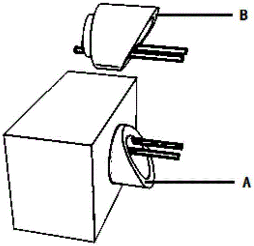
[0099] figure 1 It is a schematic diagram of a three-dimensional structure of a remote wireless power transmission device that can control the power transmission range provided by this embodiment. The above-mentioned cylindrical wrapping layer is used for the reinforced wrapping layer, and the material parameters are derived from the above-mentioned transformation function f(r). The wire segments of the cylindrical reinforced wrapping layer represent the transmitting module and the receiving module respectively, and the transmitting module and its cylindrical reinforced wrapping layer are embedded in the cuboid bunker, which means that the transmitting module and its reinforced wrapping layer can be used as infrastructure along the Continuous, segmented or fixed-point traffic routes are set under the road surface or near the road. If the receiving module and its enhanced wrapping are installed in the vehicle, it can be powered wirelessly at all times while driving on the road....

Embodiment 2

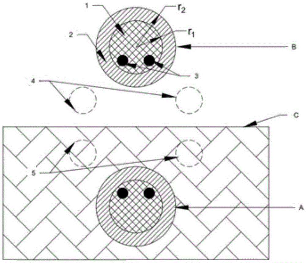
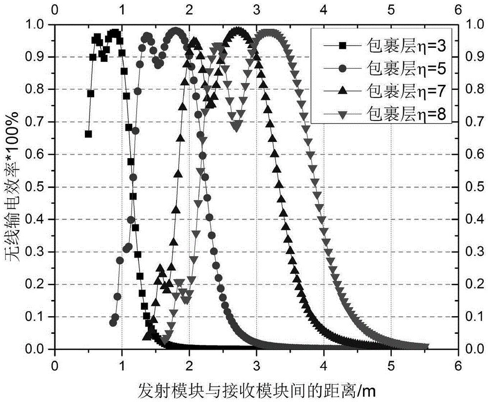
[0103] image 3 It is a graph of the wireless power transmission efficiency changing with distance obtained through numerical simulation calculation in this embodiment. This figure is obtained in the case of a remote wireless power transmission device with a controllable power transmission range as follows: image 3 The wrapping layer used in the embodiment is also a cylindrical wrapping layer, which is also derived by f(r) in the aforementioned technical solution. Unlike the embodiment 1 of the previous schematic diagram, only the transmitting module is wrapped with a reinforced wrapping layer, but the receiving module There is no enhanced wrapping layer outside, and no shelter is set up (or the material parameters of the shelter adopt the dielectric constant and magnetic permeability of vacuum). The geometric dimensions of the cross-section of the transmitting module or the receiving module wrapped with the enhanced wrapping layer are all less than 1 meter, and the radius o...


PUM


Abstract

The invention provides a long-distance wireless transmission device with a controllable transmission range, which comprises a transmission transmitting module, a wireless transmission efficiency enhancing and covering layer, and a receiving module, wherein the transmitting module converts electric energy into an electromagnetic wave; the enhancing and covering layer effectively enhances coupling strength between the transmitting module and the receiving module through changing an electromagnetic wave near field distribution mode; and the receiving module receives the electromagnetic wave and converts the electromagnetic wave into the electric energy. The transmission transmitting module and the wireless transmission efficiency enhancing and covering layer can serve as infrastructures to be arranged along a traffic route below or near the road in a continuous, segmented or fixed point mode, and wireless transmission is provided for a long-distance static or dynamic object provided with the receiving module; and the device can also be used in a building, and wireless transmission is carried out on equipment in an effective range.

Description

technical field [0001] The invention relates to the technical field of wireless power transmission, in particular to a long-distance wireless power transmission device that does not require impedance coupling of a transmitting and receiving module and can control a power transmission range. Background technique [0002] In recent years, wireless power transmission technology has begun to be used in many mobile power devices, especially electric vehicles and electronic digital products. At present, the wireless power transmission technology actually used basically adopts the electromagnetic induction of the electromagnetic coil at a short distance or the magnetic coupling form of a long distance for wireless power transmission. These technologies require that the relative positions of the transmitting device and the receiving device be fixed. Once their relative positions deviate, the transmission efficiency of wireless power transmission will quickly decrease; and these wire...

Claims


Application Information

Patent Timeline
IPC IPC(8): H02J17/00
Inventor 罗旭东祝林马红孺
Owner SHANGHAI JIAO TONG UNIV
Why Eureka
Try Eureka