Chest cavity drainage tube

A drainage tube and chest tube technology, applied in the field of chest drainage tubes, can solve the problems of increasing pain and infection, increasing patient pain, inconvenience, etc., and achieve the effects of reducing pain and infection probability, increasing mobility, and convenient operation

Inactive Publication Date: 2016-02-10
THE FIRST AFFILIATED HOSPITAL OF SOOCHOW UNIV
View PDF6 Cites 3 Cited by
  • Summary
  • Abstract
  • Description
  • Claims
  • Application Information

AI Technical Summary

Problems solved by technology

Therefore, after upper lobectomy, two chest drainage tubes are often placed in two incisions in the chest. This operation increases the pain and the probability of infection of the patient, and limits the mobility of the patient. If there is a chest drainage tube that can be used immediately Placed on the top of the chest for exhaust and at the costophrenic angle for drainage, it can greatly reduce the patient's pain and infection probability, and increase the patient's mobility
On the other hand, the cross-section of the traditional chest drainage tube is circular, which is not conducive to reducing the compression of the intercostal nerves, and the patient is prone to pain
[0004] In addition, some patients (such as postoperative empyema, anastomotic leak after esophageal cancer, etc.) need to perform pleural irrigation. If a traditional chest drainage tube is used, two chest tubes need to be placed, which increases the pain of the patient and restricts the movement of the patient, which is not conducive to The patient recovers, and flushing needs to inject fluid (normal saline, dilute iodine solution, etc.) from a chest tube, requiring several adapters, which is extremely inconvenient to use

Method used


Image

  • Chest cavity drainage tube
  • Chest cavity drainage tube

Examples


Embodiment Construction

[0022] The technical solutions of the present invention will be clearly and completely described below through specific embodiments. Apparently, the described embodiments are only some of the embodiments of the present invention, but not all of them. Based on the embodiments of the present invention, all other embodiments obtained by persons of ordinary skill in the art without creative efforts fall within the protection scope of the present invention.

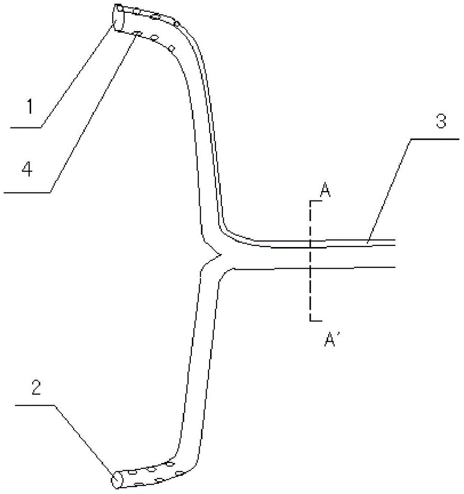
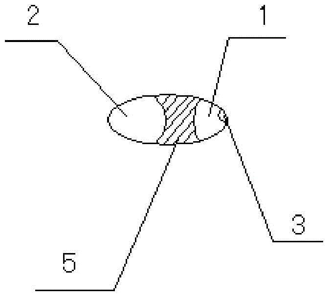
[0023] Such as figure 1 As shown, a chest drainage tube of the present invention is in a Y shape, and the chest drainage tube includes an upper chest tube 1 and a lower chest tube 2 . Before the above-mentioned chest drainage tube is at the Y-shaped bifurcation, the upper chest tube 1 and the lower chest tube 2 are in the same sleeve, and the cross section of the sleeve is oval, and the tube is sleeved on the upper chest tube and the lower chest tube. Separate support walls 5 are provided between the tubes. Under the action...


PUM


Abstract

The invention discloses a chest cavity drainage tube. The chest cavity drainage tube is in a Y shape, and comprises an upper chest tube and a lower chest tube; the upper chest tube and the lower chest tube of the chest cavity drainage tube are positioned in the same tube sleeve in front of the crotch of the Y shape; the cross section of the tube sleeve is elliptical; a separating supporting wall is formed at the position, between the upper chest tube and the lower chest tube, of the tube sleeve; a thin flushing tube used for flushing the chest cavity is arranged in the upper chest tube. According to the chest cavity drainage tube, two incisions which are required to be formed in the chest of a patient when a traditional chest cavity drainage tube is used can be reduced to one incision, so that the pain of the patient and the wound infection rate can be effectively reduced.

Description

technical field [0001] The invention relates to the field of medical devices, in particular to a chest drainage tube for draining gas or liquid in the chest cavity. Background technique [0002] A chest drain is a device used to drain air or fluid from the chest cavity. Clinically, it is commonly used in the treatment of diseases such as pneumothorax, pleural effusion, and hydropneumothorax. In addition, chest drainage tubes are routinely placed after thoracic surgery to facilitate the removal of postoperative fluid and gas in the pleural cavity, thereby promoting lung recruitment. [0003] At present, in clinical practice, two chest drainage tubes are usually placed in upper lobectomy, one is placed on the top of the chest mainly for exhaust, and the other is placed at the costophrenic angle mainly for drainage. Therefore, after upper lobectomy, two chest drainage tubes are often placed in two incisions in the chest. This operation increases the pain and the probability o...

Claims


Application Information

Patent Timeline
Patent Type & Authority Applications(China)
IPC IPC(8): A61M25/14
Inventor 倪斌
Owner THE FIRST AFFILIATED HOSPITAL OF SOOCHOW UNIV
Why Eureka
Try Eureka