
A mineral processing device

A processing device, technology of mineral products

Active Publication Date: 2017-05-31
永州市鸿鑫锰业有限公司
View PDF8 Cites 0 Cited by
  • Summary
  • Abstract
  • Description
  • Claims
  • Application Information

AI Technical Summary

Problems solved by technology

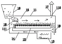
[0002] Existing mineral product processing devices generally include a dryer, material sorting machine, material receiving container and dust collector. The mineral material with high density is below the water flow, and the slag with low density is above the water flow. This material selection machine needs a lot of water, and the mineral material also pollutes water, and the separation efficiency is low.
Existing drying is carried out in a drying tunnel, which is equipped with a conveyor belt. The mineral material is transported in the conveyor belt while drying in the tunnel. Since the wet mineral material is statically stacked in the conveyor belt, the mineral material is dried Slow, and the mineral materials inside are not easy to dry, and the drying efficiency is low
In the field of ore processing, it is often necessary to transport the ore from the stockyard to the processing equipment. The existing transportation generally uses a conveyor belt, and the loading is carried by a loader through a funnel to one end of the conveyor belt, and then transported to the mineral material processing equipment through the conveyor belt. , because the processing capacity of the ore processing equipment is fixed, and the amount that the loader adds to the conveyor belt through the funnel is not easy to control, the amount of ore transported is uneven, and the distribution of ore in the conveyor belt is more in the middle and less on both sides , it is difficult to meet the normal use requirements of processing equipment

Method used


Image

  • A mineral processing device
  • A mineral processing device
  • A mineral processing device

Examples


Embodiment Construction

[0059] Below in conjunction with accompanying drawing and embodiment describe in detail:

[0060] Such as figure 1 As shown, the first mineral product processing device of the present invention includes a dryer 2, a wind separator 9, a material receiving container 4 and a dust collector 5, and the dryer 2 sends the dried ore to the wind through a conveyor belt 6. The feed port 8 of the separator 9, the air separator 9 screens out the ore, the air separator 9 sends the remaining tailings through the pipeline 7 to the receiving container 4, and the dust discharged from the receiving container 4 is sent to the dust collector 5 processes, and air separator 9 is used as material selector here.

[0061] Such as figure 2 As shown, the second mineral product processing device of the present invention includes a dryer 2, a first distributing machine 1, a second distributing machine 3, a winnowing machine 9, a material receiving container 4 and a dust remover 5, and the first distrib...


PUM


Abstract

The invention discloses a mineral product processing device which comprises a dryer, a winnowing machine, a receiving container and a deduster. Dried ore is sent to a feeding port of the winnowing machine through the dryer. Mineral materials are selected out through the winnowing machine. Tailing left after selecting is sent into the receiving container through the winnowing machine. Dust discharged by the receiving container is sent to the deduster to be processed. Or, the mineral product machining device comprises a dryer, a first distributing machine, a second distributing machine, a winnowing machine, a receiving container and a deduster. The first distributing machine supplies materials to the dryer. Dried ore is sent to the second distributing machine through the dryer. The ore is sent to a feeding port of the winnowing machine through the second distributing machine. Mineral materials are selected out through the winnowing machine. Tailing left by selecting is sent into the receiving container through the winnowing machine. Dust discharged by the receiving container is sent to the deduster to be processed. The mineral product processing device is good in using effect and high in machining efficiency.

Description

technical field [0001] The invention relates to a mineral product processing device, which belongs to the technical field of mineral product processing machinery. Background technique [0002] Existing mineral product processing devices generally include a dryer, material sorting machine, material receiving container and dust collector. The mineral material with high density is below the water flow, and the slag with low density is above the water flow. This material separator needs a lot of water, the mineral material also pollutes the water, and the separation efficiency is low. Existing drying is carried out in a drying tunnel, which is equipped with a conveyor belt. The mineral material is transported in the conveyor belt while drying in the tunnel. Since the wet mineral material is statically stacked in the conveyor belt, the mineral material is dried Slow, and the mineral materials inside are not easy to dry, and the drying efficiency is low. In the field of ore proc...

Claims


Application Information

Patent Timeline
Patent Type & Authority Patents(China)
IPC IPC(8): B07B7/00B07B11/06B04C9/00F26B17/20F26B25/00
CPCB04C9/00B07B7/00B07B11/06F26B17/20F26B25/00
Inventor 周大恩
Owner 永州市鸿鑫锰业有限公司
Learn More