Powder metallurgy die of efficient drainage structure

A drainage structure and powder metallurgy technology, applied in the field of powder metallurgy, can solve problems such as low drainage efficiency, damage to parts, and inability to separate water and powder.

Inactive Publication Date: 2016-02-10
FOSHAN CONSTANT HYDRAULIC MACHINERY
View PDF10 Cites 1 Cited by
  • Summary
  • Abstract
  • Description
  • Claims
  • Application Information

AI Technical Summary

Problems solved by technology

As a result, during the pressing process, the water in the wet powder enters the water storage chamber 30 above the cavity 10 through the drainage pipe 20, and stays in the water storage chamber 30 and the drainage pipe 20. After the parts are formed, the mold is opened, and the Water can only be discharged from the water suction port 40 provided on the upper half mold 11 under pressure, so this negative pressure water absorption method is only to achieve the purpose of separating metal powder and water during the part forming process; this drainage method

Method used


Image

  • Powder metallurgy die of efficient drainage structure
  • Powder metallurgy die of efficient drainage structure
  • Powder metallurgy die of efficient drainage structure

Examples


Embodiment Construction

[0020] The technical solutions of the present invention will be further described below in conjunction with the accompanying drawings and through specific implementation methods.

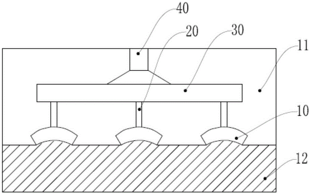
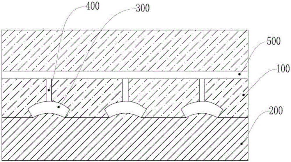
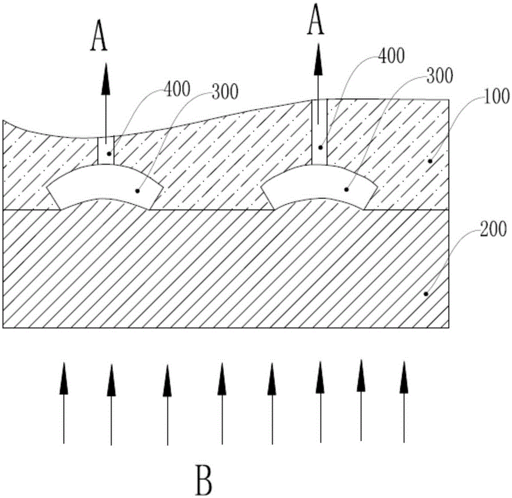
[0021] Such as Figure 2-3 As shown, a powder metallurgy mold with an efficient drainage structure includes a lower mold 200, an upper mold 100 and a molding cavity 300; the molding cavity 300 is a closed cavity, which is covered by the upper mold 100 and the lower mold 200 formed; above the molding cavity 300 are provided with a water absorption channel 400 and an air flow channel 500, the air intake end of the air flow channel 500 is connected to the air source, and the exhaust end of the air flow channel 500 communicates with the outside; the water absorption channel One end of 400 communicates with the molding cavity 300 , and the other end communicates with the airflow channel 500 . After the upper mold 100 and the lower mold 200 are closed to form the molding cavity, wet powder is injected in...


PUM


Abstract

The invention relates to the field of powder metallurgy, and particularly relates to a powder metallurgy die of an efficient drainage structure. The powder metallurgy die comprises a lower die, an upper die and a forming cavity, wherein the forming cavity is a closed containing cavity which is formed in a way that the upper die and the lower die are closed, a water absorption passage and an air flow passage are arranged above the forming cavity, one end of the water absorption passage is communicated with the forming cavity, and the other end of the water absorption passage is communicated with the air flow passage. Moisture in the powder metallurgy die is blown out of the die under the action of air flow, so that water in the die is drained in time, and the drainage resistance of the water absorption passage is reduced; additionally, extruded water is reduced at a late stage of forming, so that residual water in the forming cavity and the water absorption passage can be actively absorbed under the absorption action of the air flow, the drainage time when a part is formed is greatly extended, the forming efficiency of the powder metallurgy die is improved, and the probability that the residual water drips on the formed part from the forming cavity and damages are caused when the die is opened is greatly reduced.

Description

technical field [0001] The invention relates to the field of powder metallurgy, in particular to a powder metallurgy mold with an efficient drainage structure. Background technique [0002] In the field of powder metallurgy, it is necessary to press the powder material with moisture to form parts through molding dies. At present, wet powder molding machines are often used in China to complete the molding process of parts; the water needs to be discharged during the compression molding process after the injection of wet powder, that is, the slurry. Since the wet powder is a slurry-like raw material, it is required to form a closed cavity inside the forming mold, and at the same time, it is determined that the direction of water discharge is only upward. [0003] Existing wet powder molding machines all adopt the negative pressure water absorption method to discharge the moisture in the wet powder during molding. Such as figure 1 As shown, the forming mold includes an upper...

Claims


Application Information

Patent Timeline
IPC IPC(8): B22F3/03
Inventor 权晋花陈国华李明黄志伟何景晖
Owner FOSHAN CONSTANT HYDRAULIC MACHINERY
Why Eureka
Try Eureka