Nuclear power plant unipolar magnetic control band electrode electroslag surfacing method and device

A technology for electroslag surfacing and nuclear power plants, applied in the field of unipolar magnetically controlled strip-polar electroslag surfacing welding methods and devices in nuclear power plants, which can solve the problems of affecting the accessibility of welding torches, collisions, and magnetic control modules affecting welding accessibility, etc.

Active Publication Date: 2016-02-10
中广核工程有限公司 +1
5 Cites 3 Cited by

AI-Extracted Technical Summary

Problems solved by technology

[0004] However, the magnetic control modules of the double magnetron strip electroslag surfacing device are respectively placed at the positions of the width direction of the welding strip (ie, the left and right sides of the width direction of the welding strip), which affects to a certain extent the welding torch when performing strip ele...

Method used

Visible, in the embodiment of the present invention, by installing a position-adjustable single magnetic control device on the electroslag overlay welding device with poles, the dual magnetron electroslag electroslag that exists in the prior art is effectively solved The magnetic control module of the...

Abstract

The invention discloses a nuclear power plant unipolar magnetic control band electrode electroslag surfacing method and device. The problem that a magnetic control module of an existing double magnetic control band electrode electroslag surfacing device affects the welding accessibility is solved. The nuclear power plant unipolar magnetic control band electrode electroslag surfacing device comprises a fusion welding power source, a band electrode welding material, a band electrode feeding module, a contact tube, a single magnetic control module and a magnetic control power source. The nuclear power plant unipolar magnetic control band electrode electroslag surfacing method comprises the steps that S1, the fusion welding power source is connected with the contact tube, so that the band electrode welding material is charged, and the band electrode feeding module conveys the charged band electrode welding material to the surface of a large container; S2, the fusion welding power source is connected with the large container, a current loop is formed when the charged band electrode welding material makes contact with the fusion welding power source, slag conducts electricity and generates resistance heat, and a molten bath is formed; and S3, the magnetic control power source supplies electricity to the single magnetic control module, and then undercut is prevented from being generated when the molten bath forms a weld bead. The installation position of the single magnetic control module can be adjusted, so that band electrode electroslag surfacing conducted on a boss accessory area of the large container is achieved.

Technology Topic

SlagElectricity +9

Image

  • Nuclear power plant unipolar magnetic control band electrode electroslag surfacing method and device
  • Nuclear power plant unipolar magnetic control band electrode electroslag surfacing method and device
  • Nuclear power plant unipolar magnetic control band electrode electroslag surfacing method and device

Examples

  • Experimental program(2)

Example Embodiment

[0035] Example one
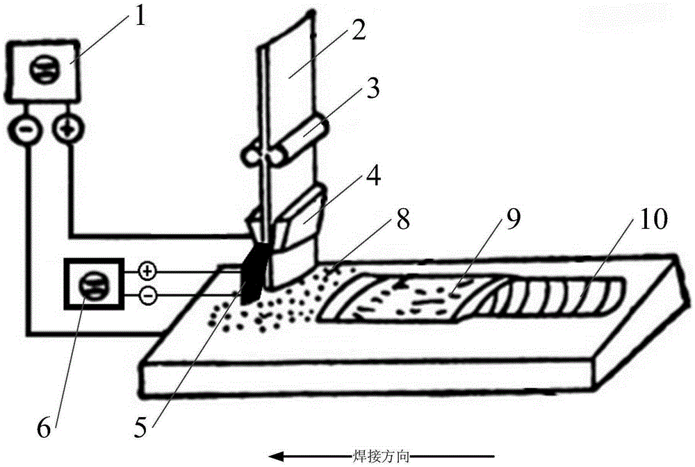
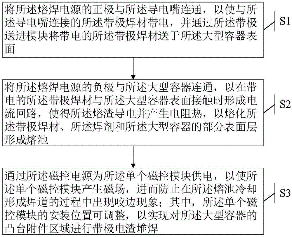
[0036] The embodiment of the present invention provides a single-pole magnetron electroslag surfacing method for nuclear power plants, which is applied to a magnetron electroslag surfacing device for surfacing corrosion-resistant layers of large vessels in nuclear power plants. Please refer to figure 1 , The strip electrode electroslag surfacing welding device includes: fusion welding power source 1, strip electrode welding material 2, strip electrode feeding module 3, contact tip 4, single magnetron module 5 and magnetron power source 6; the surface of large container 7 is laid There are flux 8 and slag 9; figure 2 As shown, the electrode electroslag surfacing method includes the following steps:
[0037] S1. Connect the positive electrode of the welding power source 1 with the contact tip 4, so that the strip electrode 2 connected to the contact tip 4 is charged, and the strip electrode is fed into the module 3 to be charged The tape electrode 2 is delivered to the surface of the large container 7;
[0038] S2. Connect the negative electrode of the fusion welding power source 1 with the large container 7 to form a current loop when the charged strip welding material 2 contacts the surface of the large container 7, so that the slag 9 is conductive And generate resistance heat to melt the strip electrode 2, the flux 8 and part of the surface layer of the large container 7 to form a molten pool;
[0039] S3. Supply power to the single magnetron module 5 through the magnetron power supply 6 so that the single magnetron module 5 generates a magnetic field, thereby preventing undercutting during the process of cooling the molten pool to form the weld bead 10 Wherein, the installation position of the single magnetron module 5 can be adjusted to realize the electrode electroslag surfacing on the attachment area of ​​the boss of the large container 7. Wherein, the magnetron module 5 forms a magnetron electrode when it is energized, and the magnetron electrode is an N pole.
[0040] In the specific implementation process, in terms of parameters, the difference between single magnetron and double magnetron is mainly the difference in magnetron current. Under reasonable single magnetron current and reasonable welding process parameters, no undercut defects can be obtained. And the performance meets the required surfacing weld, so the single magnetron can achieve the same effect as the double magnetron in preventing undercut. In this embodiment, the welding process parameters provided below can obtain a surfacing weld with good performance, and the weld has no undercut defects:
[0041] 1) The magnetron current delivered by the magnetron power supply 6 to the magnetron module 5 is 2.0-2.1A;
[0042] 2) The welding current provided by the welding power source 1 is 1000-1100A, and the welding voltage is 23-26V;
[0043] 3) The welding speed of the electrode electroslag surfacing welding device is 190-230 mm/min.
[0044] Austenitic stainless steel has good plasticity, toughness, weldability, corrosion resistance and non-magnetic or weak magnetic properties. It has good corrosion resistance in oxidizing and reducing media. Nickel-based corrosion resistant alloys have excellent stress corrosion resistance in high temperature environments containing water. In this scheme, in order to improve the corrosion resistance of the large nuclear power plant container surface, a certain thickness of stainless steel or nickel-based alloy is surfacing welded on the surface of the large nuclear power plant container. The strip welding material used in the unipolar magnetron strip electrode electroslag surfacing device 2Using 60mm×0.5mm stainless steel welding strip or 60mm×0.5mm nickel-based alloy welding strip. That is, the single-pole magnetron electroslag surfacing device of this scheme is suitable for 60mm×0.5mm stainless steel electroslag surfacing and 60mm×0.5mm nickel-based alloy electroslag surfacing.
[0045] In the surfacing test process of the first embodiment, use such as figure 1 The unipolar magnetron electroslag surfacing device shown image 3 The base material 31 shown is surfacing welding, the welding current ranges from 1000A to 1100A, the preheating temperature is controlled between 125°C and 150°C, and the interlayer temperature is controlled within 225°C. in image 3 Among them, the base material 31 used is SA508Gr3Cl2 low-alloy steel (which is the same material as the large-scale nuclear power plant container), and the test plate length (a) × width (b) × height (c) is 410mm × 280mm × 100mm; strip welding material 2 It is an Inconel52M nickel-based alloy, the size is 60×0.5mm, the flux 8 is INCOFLUXESS2, and the welding method is horizontal electrode electroslag surfacing. The schematic diagram of surfacing welding bead 32 is still as follows image 3 As shown, the overlap between each bead is 7-9mm. After the surfacing welding is completed, post heat treatment is carried out. The post heat treatment process: heat the base material 31 and the weld bead 32 to a temperature range of 250°C to 300°C for 4 hours. After post-heating is completed, post-welding stress-relieving heat treatment is performed. Post-welding stress-relieving heat treatment process: heat the base material 31 and the weld bead 32 to a temperature range of 595℃~610℃ for 16.5 hours. The non-destructive testing during the entire welding process includes: (1) Visual inspection and dimensional inspection of the surface to be surfacing; (2) MT inspection of the surface to be surfacing; (3) Visual inspection and dimensional inspection of the surfacing layer after welding; (4) PT inspection of surfacing layer after welding; (5) UT inspection of surfacing layer after welding; (6) PT inspection of surfacing layer after heat treatment; (7) UT inspection of surfacing layer after heat treatment; (8) Macro metallographic sample PT an examination. After the final heat treatment, the welded joints are sampled to analyze the deposited metal composition, hardness test (surfacing layer, heat-affected zone, base metal), and macroscopic metallographic inspection perpendicular to the surfacing direction (surfacing layer, heat-affected zone, mother metal). Material), microscopic metallographic inspection (surfacing layer, heat-affected zone) perpendicular to the surfacing direction, guided bending test. The analysis and testing results show that all the results meet the requirements, that is, it can meet the forming and performance requirements of the surfacing weld.
[0046] For the question of how to improve the accessibility of the welding gun, such as figure 1 As shown, the single magnetron module 5 of the single-pole magnetron electroslag surfacing welding device is installed on one side in the width direction of the electrode welding material 2, and the magnetron module 5 occupies a certain space position. Welding direction ( figure 1 The direction indicated by the middle arrow) is perpendicular to the width of the strip welding material 2. Therefore, during the surfacing process, the single magnetron module 5 can be adjusted to the left or right of the contact tip 4 according to the position of the boss, so as to realize the alignment of the boss The nearby area is implemented with electrode surfacing to improve the welding accessibility of the electrode electroslag surfacing device.

Example Embodiment

[0047] Example two
[0048] Based on the same inventive concept, please refer to figure 1 , The embodiment of the present invention also provides a single-pole magnetron strip electrode electroslag surfacing device for nuclear power plants, including: fusion welding power source 1, strip electrode welding material 2, strip electrode feeding module 3, conductive nozzle 4, magnetron module 5 and the magnetron power supply 6; the electrode electroslag surfacing welding device is used for surfacing the corrosion-resistant layer of the large vessel 7 of the nuclear power station. The surface of the large vessel 7 is laid with flux 8 and slag 9, among which,
[0049] The tape feeding module 3 is connected with the tape welding material 2 for sending the tape electrode 2 to the surface of the large container 7 during the surfacing process;
[0050] The contact tip 4 is arranged on the strip welding material 2 and connected to the positive electrode of the welding power source 1 for charging the strip welding material 2;
[0051] The negative electrode of the welding power source 1 is connected to the large container 7, and is used to form a current loop when the strip electrode 2 is in contact with the surface of the large container 7, so that the slag 9 conducts electricity and generates resistance heat to melt the strip electrode 2, flux 8 and part of the surface layer of the large container 7 form a molten pool, and a weld bead 10 is formed when the molten pool is cooled;
[0052] The magnetron module 5 is single, and can be optionally fixed on the left or right side of the contact tip 4, and is used to generate a magnetic field when electrically connected to the magnetron power supply 6 to prevent undercutting during surfacing.
[0053] Wherein, the magnetron module 5 forms a magnetron electrode when it is energized, and the magnetron electrode is an N pole. Strip pole welding material 2 adopts 60mm×0.5mm stainless steel welding strip or 60mm×0.5mm nickel-based alloy welding strip. The magnetron current delivered by the magnetron power supply 6 to the magnetron module 5 is 2.0-2.1A. The welding current provided by the fusion welding power source 1 is 1000-1100A, and the welding voltage is 23-26V; the welding speed of the electrode-electroslag surfacing device is 190-230mm/min.
[0054] According to the above description, the above-mentioned single-pole magnetron electroslag surfacing device for nuclear power plants is used to realize the above-mentioned single-pole magnetron electroslag surfacing method for nuclear power plants. Therefore, one or more embodiments of the device and the One or more embodiments of the method are the same, and will not be repeated here.
[0055] In a word, by adopting the unipolar magnetron electroslag surfacing device of the present invention and the implementation of the unipolar magnetron electroslag surfacing method of the present invention, while meeting the requirements of the forming and performance of the surfacing weld bead, it improves The accessibility of the torch for electroslag surfacing welding can be used for stainless steel electroslag surfacing or nickel-based alloy electroslag surfacing in the area near the boss. Compared with the previous manual arc surfacing near the boss The method greatly improves the welding efficiency and has very important engineering practical value.
[0056] Those skilled in the art should understand that the embodiments of the present invention may be provided as methods, systems, or computer program products. Therefore, the present invention may adopt the form of a complete hardware embodiment, a complete software embodiment, or an embodiment combining software and hardware. Moreover, the present invention may be in the form of a computer program product implemented on one or more computer-usable storage media (including but not limited to disk storage, CD-ROM, optical storage, etc.) containing computer-usable program codes.

PUM

no PUM

Description & Claims & Application Information

We can also present the details of the Description, Claims and Application information to help users get a comprehensive understanding of the technical details of the patent, such as background art, summary of invention, brief description of drawings, description of embodiments, and other original content. On the other hand, users can also determine the specific scope of protection of the technology through the list of claims; as well as understand the changes in the life cycle of the technology with the presentation of the patent timeline. Login to view more.
Why Eureka
Try Eureka