Compressor rotor blade groove machining clamping tool with supporting frame

A compressor rotor and blade slot technology, applied in metal processing equipment, metal processing mechanical parts, clamping and other directions, can solve problems such as endangering the life safety of operators, time-consuming and laborious clamping reliability, and impact on business capabilities, to avoid Uncertainty, the effect of realizing semi-automatic control

Inactive Publication Date: 2016-02-10
CHONGQING JINCHEN MACHINERY MFG
View PDF5 Cites 2 Cited by
  • Summary
  • Abstract
  • Description
  • Claims
  • Application Information

AI Technical Summary

Problems solved by technology

[0002] The compressor is a driven fluid machine that elevates low-pressure gas to high-pressure gas. It is the heart of the refrigeration system. It sucks low-temperature and low-pressure refrigerant gas from the suction pipe, and drives the piston to compress it through the operation of the motor. The exhaust pipe discharges high-temperature and high-pressure refrigerant gas to provide power for the refrigeration cycle, thereby realizing the refrigeration cycle of compression→condensation (heat release)→expansion→evaporation (heat absorption), and the rotor of the compressor core is the work of the entire compressor The core component of the rotor blade groove is traditionally processed by manual clamping. Manual clamping is not only time-consuming and labor-intensive, but more importantly, the clamping reliability is seriously affected by the operator's business ability, and once the rotor is processed, the clamping reliability is not enough. Not only affects the pass rate of the product, but also may endanger the life safety of the operator

Method used


Image

  • Compressor rotor blade groove machining clamping tool with supporting frame
  • Compressor rotor blade groove machining clamping tool with supporting frame

Examples


Embodiment Construction

[0014] The present invention will be further described below in conjunction with the embodiments and accompanying drawings.

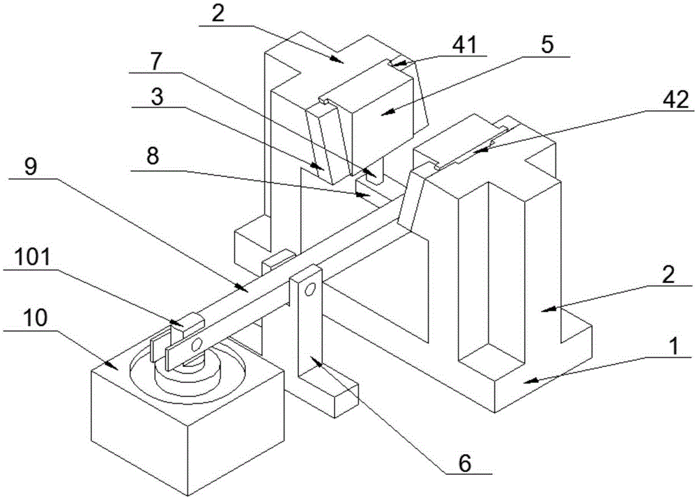
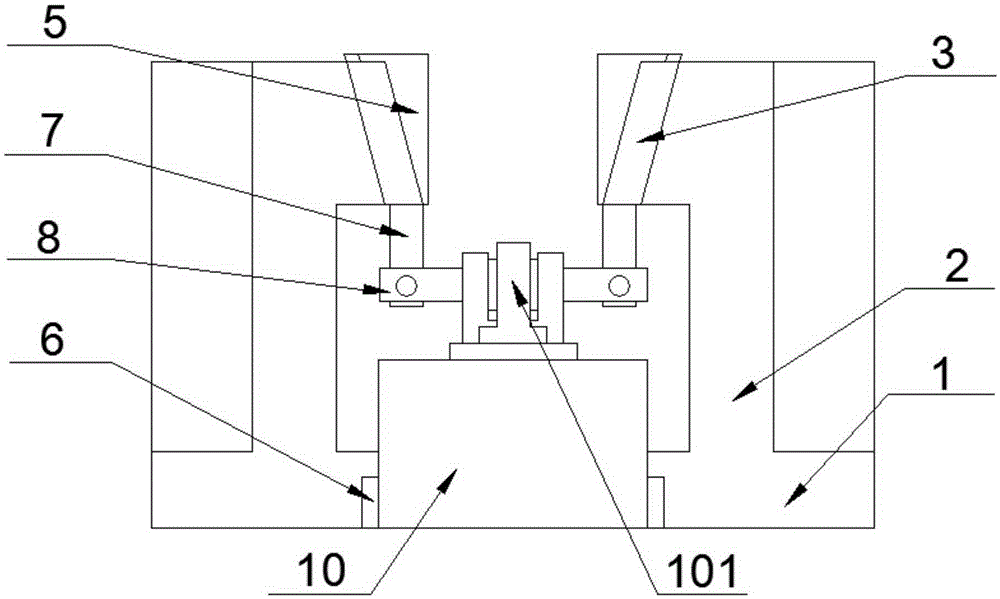
[0015] Such as figure 1 and figure 2 As shown, a supported compressor rotor blade groove processing and clamping tool includes a clamping device, and the clamping device includes a base 1, and two clamping blocks 2 are arranged in parallel on the base 1, two The clamping blocks 2 are arranged opposite to and perpendicular to the base 1, and the opposite side tops of the two clamping blocks 2 are fixedly equipped with clamping slide mounting seats 3, and the clamping slide mounting seats 3 are respectively provided with There are a first guide chute 41 and a second guide chute 42, the first guide chute 41 and the second guide chute 42 are respectively provided with a clamping slide 5, the first guide chute 41 and The second guide chute 42 is a chute whose upper end is inclined outward, and the inclination angle of the two is consistent. 8. Both ends ...


PUM


Abstract

The invention discloses a compressor rotor blade groove machining clamping tool with a supporting frame. The compressor rotor blade groove machining clamping tool comprises a clamping device. The clamping device comprises a base, and two clamping blocks are arranged on the base and are arranged in a direct facing mode. Clamping sliding plate mounting seats are arranged on the opposite side faces of the clamping blocks respectively, and are provided with a first guide sliding groove and a second guide sliding groove respectively, and the upper end of the first guide sliding groove and the upper end of the second guide sliding groove are inclined outwards. Clamping sliding plates are arranged in the first guide sliding groove and the second guide sliding groove respectively, the lower ends of the clamping sliding plates are provided with connecting columns respectively, and the lower ends of the connecting columns are hinged to the two ends of a transmission cross rod respectively. An air cylinder or oil cylinder is arranged on one side of the clamping device, and a transmission lever and the supporting frame are arranged between the air cylinder or oil cylinder and the clamping device. One end of the transmission lever is connected with the middle of the transmission cross rod, and the other end of the transmission lever is hinged to a piston rod of the air cylinder or oil cylinder. The transmission lever is hinged to the supporting frame. The air cylinder or oil cylinder is utilized for driving the clamping sliding plates to vertically move in the guide sliding grooves, and semi-automatic control over rotor clamping is achieved.

Description

technical field [0001] The invention relates to the field of machining fixtures, in particular to a supported compressor rotor blade slot machining and clamping fixture. Background technique [0002] The compressor is a driven fluid machine that upgrades low-pressure gas to high-pressure gas. It is the heart of the refrigeration system. It sucks low-temperature and low-pressure refrigerant gas from the suction pipe, drives the piston through the motor to compress it, and sends it to the compressor. The exhaust pipe discharges high-temperature and high-pressure refrigerant gas to provide power for the refrigeration cycle, thereby realizing the refrigeration cycle of compression→condensation (heat release)→expansion→evaporation (heat absorption), and the rotor of the compressor core is the work of the entire compressor The core component of the rotor blade groove is traditionally processed by manual clamping. Manual clamping is not only time-consuming and labor-intensive, but ...

Claims


Application Information

Patent Timeline
Patent Type & Authority Applications(China)
IPC IPC(8): B23Q3/08
CPCB23Q3/082B23Q3/062B23Q3/08B23Q2703/04
Inventor 侯得银
Owner CHONGQING JINCHEN MACHINERY MFG
Why Eureka
Try Eureka