Closed loop control of aircraft control surfaces

A control surface and aircraft technology, applied in the field of closed-loop control of aircraft control surfaces, can solve problems such as factors that cannot take into account the instantaneous performance of the aircraft

Active Publication Date: 2016-02-10
THE BOEING CO
View PDF5 Cites 12 Cited by
  • Summary
  • Abstract
  • Description
  • Claims
  • Application Information

AI Technical Summary

Problems solved by technology

However, such tables usually fail to take into account factors affecting the instantaneous performance

Method used


Image

  • Closed loop control of aircraft control surfaces
  • Closed loop control of aircraft control surfaces
  • Closed loop control of aircraft control surfaces

Examples


Embodiment Construction

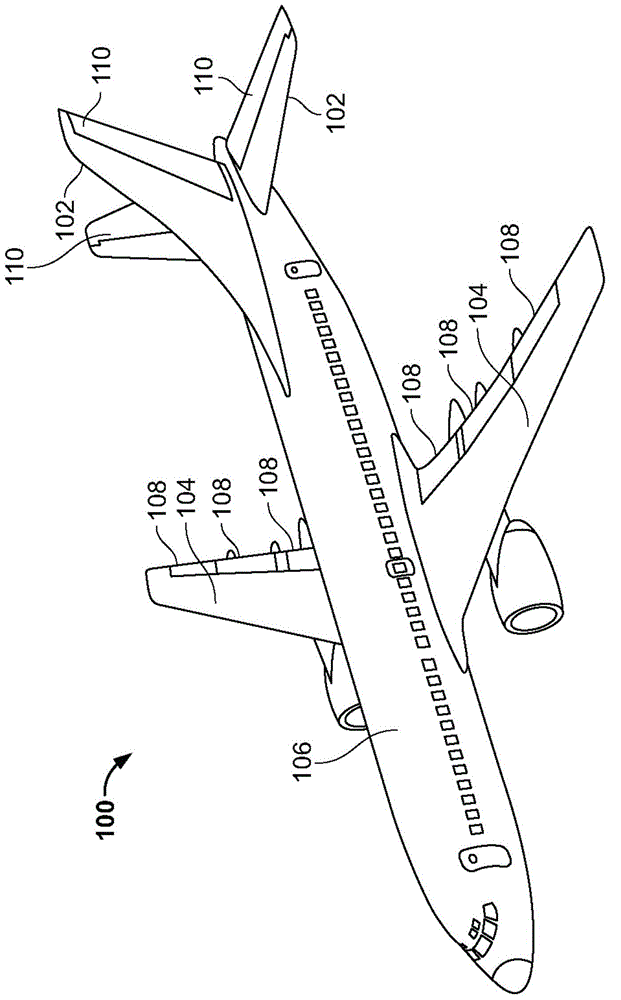
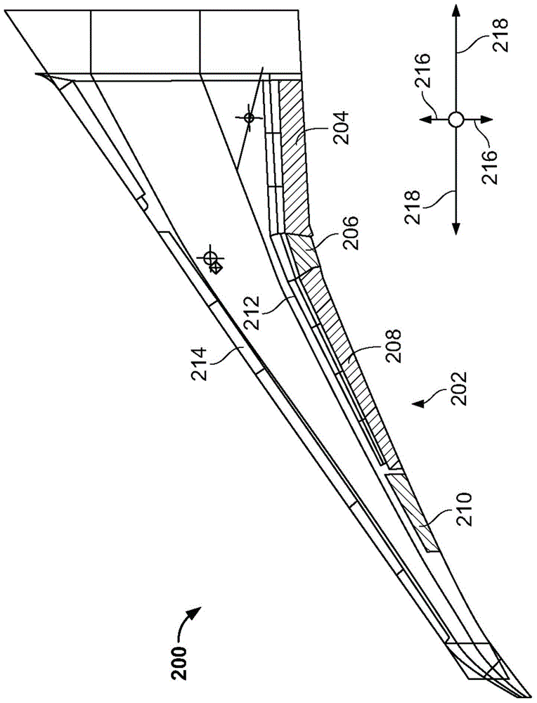
[0019] Closed-loop control of control surfaces (eg, flaps, rudder, ailerons, etc.) of an aircraft is disclosed herein. During takeoff, the control surfaces may work to provide the proper flight power to allow or assist the aircraft to take off from the runway or land. During cruise and / or takeoff of an aircraft, the position, angle or deflection of one or more control surfaces may affect the overall drag coefficient of the aircraft. Multiple control surfaces create a multidimensional problem to be solved by which the drag coefficient can be reduced (eg, minimized and / or optimized). A lower drag coefficient can improve the fuel economy of the aircraft and thus reduce fuel costs and carbon dioxide (CO2 2 ) emissions. Examples disclosed herein allow for continuous optimization of control surface positions and / or allow optimization of control surface positions based on unique and / or recent or current conditions of the aircraft (eg, weight reduction due to fuel consumption, etc.)...


PUM


Abstract

The invention provides closed loop control of aircraft control surfaces. Closed loop control method for control surfaces includes measuring a flight metric of an aircraft during flight and calculating, using a processor, a deflection of a control surface of the aircraft based on the flight metric. The disclosed method also includes adjusting the deflection to an effective deflection level based on the calculated deflection to reduce a drag coefficient of the aircraft.

Description

technical field [0001] The present invention relates generally to aircraft, and more particularly to closed loop control of aircraft control surfaces. Background technique [0002] Some aircraft employ variable surface methods to adjust the shape of an airfoil such as the trailing edge of an aircraft wing or other control surface. Adjusting the shape of the airfoil allows adjustment of lift characteristics during takeoff. Additionally, the position (eg, deflection, angle, etc.) of the airfoil may affect drag during cruise speeds. Systems that adjust airfoils during cruise to reduce drag typically rely on tabular tables of reference aircraft data (eg, table lookups) to adjust airfoils during flight. However, such tables generally fail to take into account factors that affect the instantaneous performance of the aircraft, eg, aircraft-to-aircraft variability, system variations, random disturbances, etc. Contents of the invention [0003] An example method includes measuri...

Claims


Application Information

Patent Timeline
IPC IPC(8): B64C13/16
CPCB64C9/12G05D1/0825Y02T50/30Y02T50/40B64C3/44B64C9/00B64C13/16B64D45/0005
Inventor A·J·帕基卡拉M·A·莫泽P·H·卡彭特M·R·芬恩T·S·科克S·R·毕昂斯基B·T·怀特黑德
Owner THE BOEING CO
Why Eureka
Try Eureka