
Spraying system for waste gas purifying tower
A spray system and exhaust gas purification technology, applied in chemical instruments and methods, use of liquid separators, dispersed particle separation, etc., can solve the problems of small pipe nozzle flow and spray area, easy clogging of pipe nozzles, and large number of nozzles. , to achieve the effect of easy mass production, low cost and low cost
- Summary
- Abstract
- Description
- Claims
- Application Information
AI Technical Summary
Problems solved by technology
Method used
Image

Examples
Embodiment Construction
[0014] The present invention will be further described below in conjunction with the accompanying drawings and embodiments.
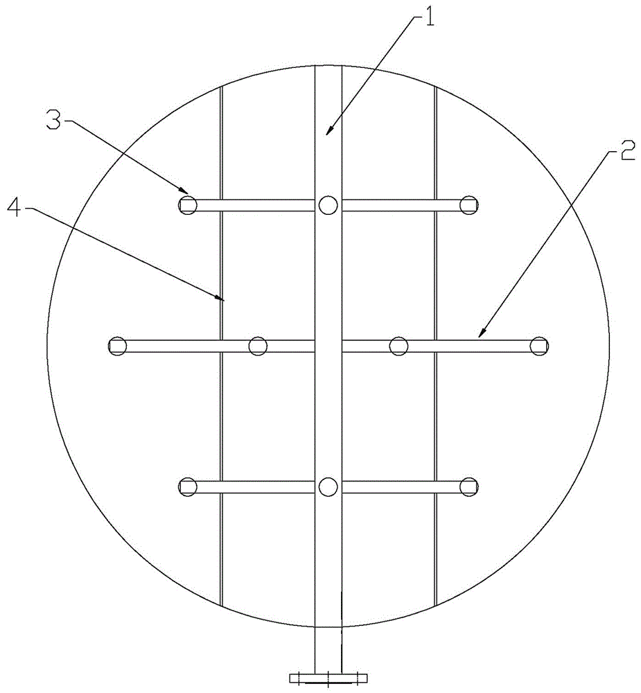
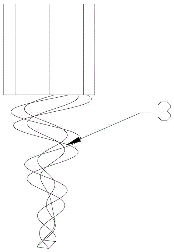
[0015] Such as Figure 1-2 Shown: a spraying system for exhaust gas purification tower, including spraying main pipe 1, spraying branch pipe 2 is evenly erected on spraying main pipe 1, and in order to strengthen the stability of spraying branch pipe 2, spraying branch pipe 2 Supported by a flat steel frame 4; 2-4 spiral nozzles 3 are uniformly arranged at the bottom of the spray branch pipe 2, and the water flow entering the spiral nozzle 3 from the spray branch pipe 2 passes through the layered interface of the spiral to produce a layered spray, the above The spiral nozzle 3 is made by injection molding, casting or kiln sintering.
[0016] In the present invention, the spiral nozzle 3 is evenly arranged at the bottom of the spray branch pipe 2. Since the interior of the spiral nozzle 3 has no structure, it is a smooth passage, a typical impact-type d...
PUM
 Abstract
Description
Claims
Application Information