Cooling system

A heat dissipation system and heat sink technology, applied in the field of heat dissipation technology, can solve the problems of low efficiency and high noise of the heat dissipation system, and achieve the effects of improving heat dissipation efficiency, low noise, and increasing air volume

Active Publication Date: 2016-02-10
LIUZHOU LIUGONG EXCAVATORS +2
View PDF8 Cites 0 Cited by
  • Summary
  • Abstract
  • Description
  • Claims
  • Application Information

AI Technical Summary

Problems solved by technology

[0009] The technical problem to be solved by the present invention is to provide a heat dissipation system for the problems of low efficiency and high noise in the existing heat dissipation system. One side of the body is open, the radiator is installed in the box, the air outlet surface of the radiator is facing the opening of the box, and the periphery of the radiator is sealed with the side wall of the box. connected, the first injector is installed on the air intake side of the radiator, the nozzle of the first injector faces the air intake surface of the radiator, and the first injector is connected to the turbocharger device through a pipeline , the air agitated by the turbocharging device is ejected from the first injector through the pipeline, and the wall plate on the air inlet side of the radiator has an air inlet for the outside air of the box to enter the box.

Method used


Image

  • Cooling system
  • Cooling system
  • Cooling system

Examples


Embodiment Construction

[0025] The specific implementation will be described below in conjunction with the accompanying drawings.

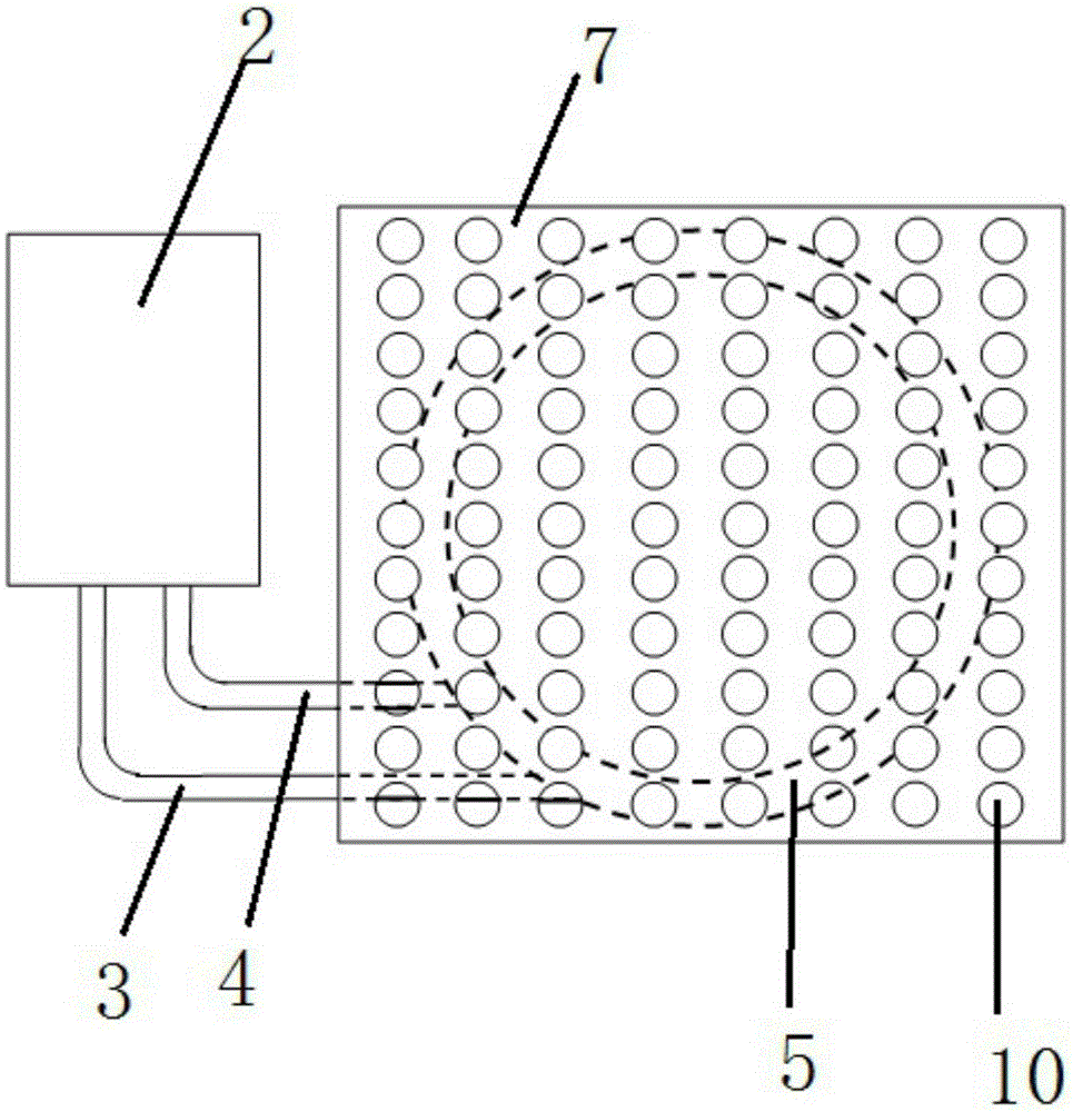
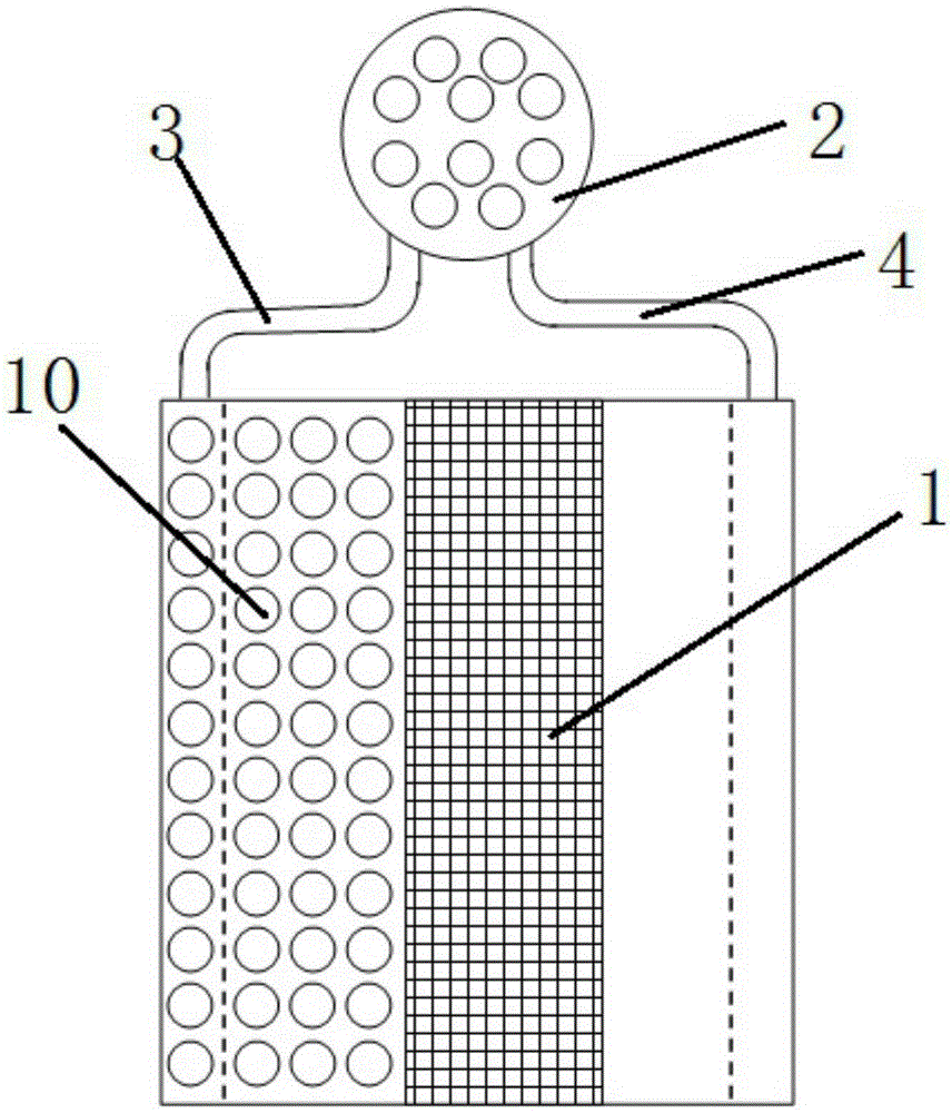
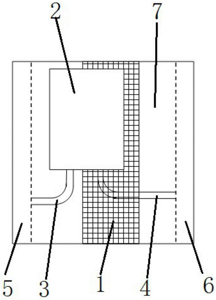
[0026] Such as Figure 1 to Figure 3 As shown, the radiator in this embodiment includes a turbocharger 2, a casing 7, a radiator 1, a first injector 5, and a second injector 6. One side of the casing 7 is open, and the radiator 1 Installed in the box body 7, the air outlet surface of the radiator 1 is facing the opening of the box body 7, the surroundings of the radiator 1 and the side walls of the box body 7 are in a sealed connection, and the first injector 5 is installed on the radiator On the air intake side of the device 1 , the nozzle of the first injector 5 faces the air intake surface of the radiator 1 , and the first injector 5 is fixedly installed in the box body 7 . The second injector 6 is installed on the air outlet side of the radiator 1, and is fixedly installed on the frame of the radiator 1. The nozzle of the second injector 6 faces away from the radiat...


PUM


Abstract

The invention relates to a cooling system so as to solve the problem that an existing cooling system is low in efficiency and high in noise. The cooling system comprises a turbo-charging device, a box, a radiator and a first ejector. One side face of the box is an opening. The radiator is mounted in the box. The air outlet face of the radiator right faces the opening of the box. The periphery of the radiator and the side walls of the box are sealed together. The first ejector is mounted on the air inlet side of the radiator. A nozzle right faces the air inlet face of the radiator. The first ejector is connected with the turbo-charging device through a pipeline. Air blown by the turbo-charging device is sprayed out by the first ejector through the pipeline. A wall plate, located on the air inlet side of the radiator, of the box is provided with an air inlet used for introducing air outside the box into the box. High-speed airflow sprayed towards the radiator from the ejector carries surrounding air to pass through the radiator together, so that air quantity is increased; the ejectors and the turbo-charging device are connected through the pipelines, the turbo-charging device is mounted on the other portion, with sufficient space, of a machine, and accordingly space limitation can be broken through.

Description

technical field [0001] The present invention relates to a heat dissipation technology, more specifically, to a heat dissipation system. Background technique [0002] With the mandatory implementation of national emission laws and regulations, the heat dissipation required by the engine of the whole machine is increasing. For example, the excavator products with three-stage emission, the heat dissipation required by the engine is more than 20% higher than that of the second stage. At the same time, exports to Europe and the United States The heat dissipation of the whole machine in the four stages is larger. Therefore, more stringent requirements are put forward for the heat dissipation efficiency of the whole machine, and the same is true in the automotive field. As the core component of the cooling system, the heat dissipation system has a great influence on the performance of the whole machine. [0003] At present, the commonly used technical solution is that the fan prov...

Claims


Application Information

Patent Timeline
Patent Type & Authority Applications(China)
IPC IPC(8): F01P5/02F01P11/10
Inventor 俞松松蒋绍军樊顺科刘剑
Owner LIUZHOU LIUGONG EXCAVATORS
Why Eureka
Try Eureka